- Joined
- Dec 9, 2021
- Messages
- 735
Things have been rather hectic for me lately, and I haven't had time to check out estate and garage sales. One item turned up that I had to jump on.
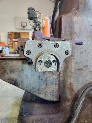
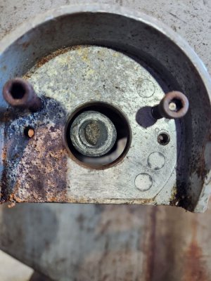
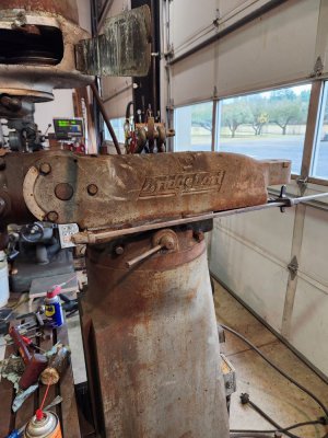
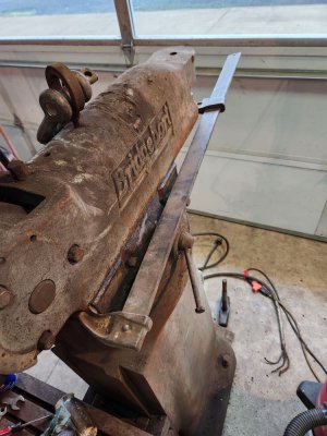
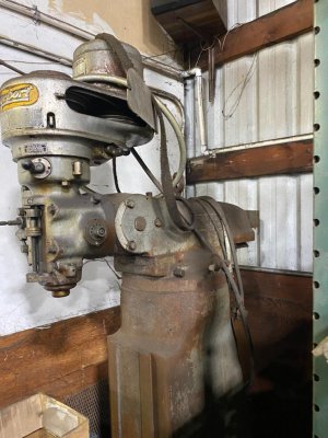
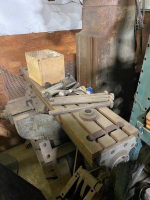
A friend keeps in touch with a machine shop his family used to own. He has a Bridgeport Type 1 mill, and expressed an interest in a part off a derelict Bridgeport they had back in a corner of their fab shop. They said he could have the part only if he hauled off the whole machine! He called me and asked if I would haul off he machine so he could get the part, which is a bearing housing on the end of the table.
When he told the shop that we would haul off the mill, they moved it out of the corner and told us to pick it up within three days! It was stored on a pallet. I was able to make time to swing by with my trailer and they put it on with a forklift, pushing it up the center over the axles with another pallet and a couple of 4x4's. This left the mill in a hard-to-reach spot. I was able to pry the pallet over to one side and could barely reach far enough with my forklift to pick it up using a chain through the lifting eye on the ram and a web strap under the head to level the lifting pressures. I cleared the fender by a half inch when backing out.
Once I got it into the shop, I started checking things out. I knew that one end of the lead screw had snapped off, and moving parts around allowed me to check check that the screw was not bent and the x-axis backlash was .040 without trying to adjust the nut. The y-axis backlash is less than .010, and both axes move smoothly and with little drag. The table turned out to be in pretty good shape, with only a couple of shallow hits from cutters. Probably better than most tables. The oil film on the quill had dried out and took a little coaxing to break free, as did the spindle bearings. Both move smoothly and easily now, and a light application of spindle oil has helped. No evidence of roughness in the spindle bearings!
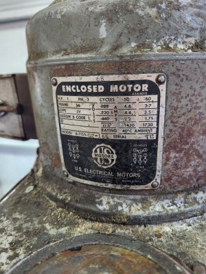
The motor spins freely by hand, and the feed freed up and works full travel, with the kick-out functioning properly. At first, the driven pulley didn't want to rotate, but an application of Kroil and soaking overnight freed it up. Now both the v-pulley and the timing belt/back gear system rotate freely.
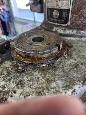
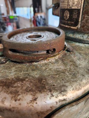
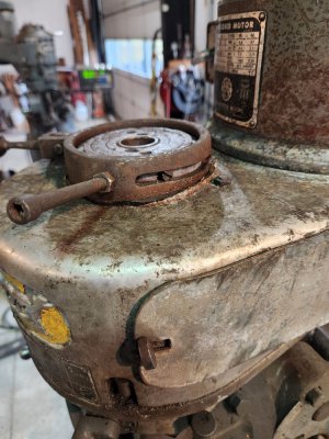
This left the cam for the high-low dog clutch as the only control still frozen up. I soaked it with Kroil and today removed the two cam follower screws that ride in the slots. I then carefully pried up on the cam ring and worked it off. There was some corrosion between the aluminum head casting and the cam ring, which I'll clean up and lubricate before reassembling it. The dog clutch assembly moves freely up and down in the head casting now.
I'm not far from being able to try it out under power. I'll set up a pigtail to plug into my 3-phase 240V power and first try the motor, then the direct and back gear drives.
If things work out, I may try to fix the lead screw by making a new end and heat shrinking it into a reamed hole in the end of the old lead screw. The damage is on the end where the bearing "floats", so it will not take thrust loads, only the torque of the handle being turned.
Here are some photos my friend took and sent me:


