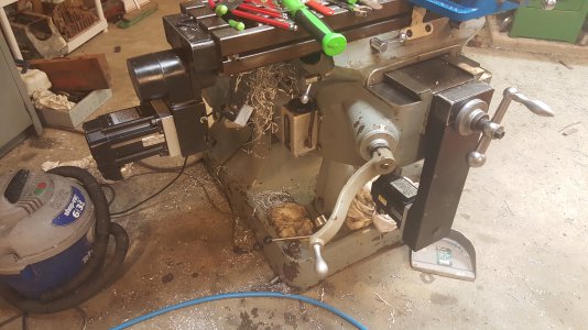
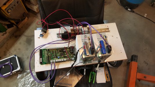
My Cnc Conversion

Cost won't include all the time I put into 'making things work'

somehow it almost never does.......if it was a business for me it would be in the red; luckily it's just a hobby and those are expected to cost money! ;)
-brino
 
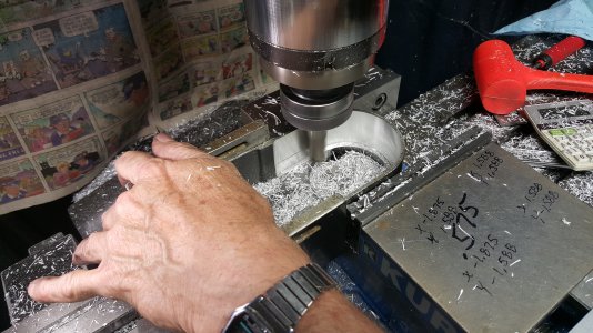
Got the housings clearanced today, done on a 2 axis prototrak k4, the picture is of the x housing, the y was nothing special to look at. Firestopper, so I asked Gary if he could run the program over and over to make this cut, it was about 5 passes, he said no, that he had to change the cutter comp and run the program each time, just an FYI for you on your controller 20151019_145458.jpg
 
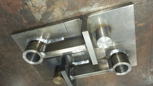
20150116_141315.jpg Interesting, I was able to make repeated passes to cut two bores (1.497") in 1/2" CR flat bar using a 3/8" end mill (cutter comp included) and manually advancing the Z between each pass, lock it down and hit go. Alternating between the two bores. I was nervous and programmed feed rate at 10 IPM. The pins and the callers you see are the bores mentioned. The pins are welded on the backside.
I was very cautious on the last pass so not to suck up the center (coupon) left by the end mill. Perhaps he chose to advance the cut by adjusting only the cutter compensation between each pass?
Looks great man!
The sharpie calculations resemble my vise too hahah.
 
He has an AGE2 controller that may be why, but I asked if he could run it continuous without having to stop between passes and have the controller just cut .015 per pass and have it repeat until say .075 was removed, he said he couldn't do that, maybe it was because of the part being machined and not knowing what exactly the end dimension needed was. We just cut it until 'looks good enough' pretty neat how he setup the y axis cuts, they were an angled cuts, he used a 18 inch ruler and set it at an angle offset to the pulley diameters and took some various measurements and programmed them in, then hit Look At program and there were two angled lines, he had picked up on the bore for the bearings as his zeros.

So he changed the cutter diameter to a smaller size in the program to make it cut .0125 each pass, hitting go each time, used a .75 cutter and ended telling the controller it was a .575, then lowered the z to cut the rest of the wall and told it It had a .580 cutter so it wouldn't rub on the shank, the cutter wasn't long enough to cut the entire wall depth.

Clever! Thats where I hope to be, I understand basic programming but not close to that level yet.
 
He has an AGE2 controller that may be why, but I asked if he could run it continuous without having to stop between passes and have the controller just cut .015 per pass and have it repeat until say .075 was removed, he said he couldn't do that, maybe it was because of the part being machined and not knowing what exactly the end dimension needed was. We just cut it until 'looks good enough' pretty neat how he setup the y axis cuts, they were an angled cuts, he used a 18 inch ruler and set it at an angle offset to the pulley diameters and took some various measurements and programmed them in, then hit Look At program and there were two angled lines, he had picked up on the bore for the bearings as his zeros.

So he changed the cutter diameter to a smaller size in the program to make it cut .0125 each pass, hitting go each time, used a .75 cutter and ended telling the controller it was a .575, then lowered the z to cut the rest of the wall and told it It had a .580 cutter so it wouldn't rub on the shank, the cutter wasn't long enough to cut the entire wall depth.
Clever! Thats where I hope to be, I understand basic programming but not close to that level yet.
 
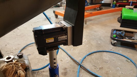
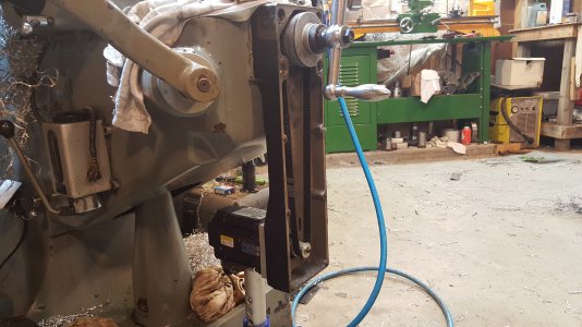
Well, she's all done, now it's time to bring the computer out and hooked all that part up. It will be trial cutting tomorrow. I need a couple set screws yet. I ended up having to make another pulley adapter, like 2.5hrs into just that piece, I used an end mill on the lathe to cut a square ended hole, well it tapered the walls somehow and overshot the dimension in the back of the hole by .005 double you tee eff. This project has so far been a ton of work, more than I had anticipated. However the experience to solve issues is well worth the effort and the tune of cash from buying turn key conversion kits. New meaning to assembly required. Not a single part was meant to work together, I still have one major issue to address, the y axis still won't move the saddle unless the dial slops out about .005, I tried numerous suggestions, including the AC bearings preloaded, nunya. So I have one last fix, oversized balls, so I'll have to take the screw apart, Mic out a ball or two and place an order. Anyway here's a parting shot of the x done. Oh yeah, my lathe head bearings starting rattlin after taking .080 cuts one after another for about .800 removed.
1445331246537-484887860.jpg
 
Back
Top