My 3 Axis DRO Install - G0731 (actually Enco)

r-mm

Registered
Registered
Joined
Jul 31, 2020
Messages
264
Hello everyone I own an Enco knee mill that is nearly identical to the model grizzly currently sell. I am going to document and ask questions about my installation of a Chinese three axis DRO system.

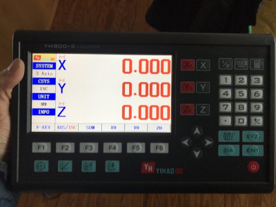
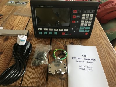
First things first I don’t know how many of you have purchased from Ali express but this was my first time and I had some caution. The transaction was incredibly smoothly I noted the length of the scales I wanted in a message to the seller, they were cut correctly and arrived in several weeks. I opted for one of the displays with a color screen and several functions. I figured if I was going to the trouble I might as well get all the functionality I can. The cost is frankly very low either way. I believe the scales are cross compatible should I ever want to upgrade or on the contrary find that the more complex display has issues but I don’t really anticipate either of those based on what others have told me.

Only issue is they sent the wrong (AU I believe?) power cable. Not really an issue, I have lots laying around.

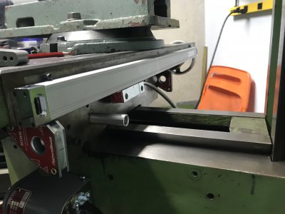
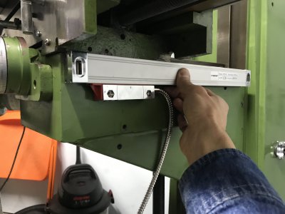
In the next posts Ill describe how I installed a bump stop and the Y axis then will be back with some questions about the X.

IMG_9914.jpg
 

Attachments

  • Photo Jan 10, 2 32 41 PM.jpg
    Photo Jan 10, 2 32 41 PM.jpg
    2.4 MB · Views: 15
  • Photo Jan 10, 1 59 27 PM.jpg
    Photo Jan 10, 1 59 27 PM.jpg
    2.4 MB · Views: 14
Last edited:
I watched Stuart de Haro's excellent youtube series on the DRO install and turned up an alum. bump stop. I made it long as my vise presently crashes the Z axis dovetails before the scales would but I can shorten it if needed.

The X axis was pretty straightforward: big old flat surface to work with. I am getting all the axes loose mounted before dialing any of them in. For that reason I only drilled one hole for the reader head. The scales have long slotted holes, the reader heads have no adjustability if you install them as I plan to, with no brackets where possible.
 

Attachments

  • Photo Feb 05, 7 37 24 PM.jpg
    Photo Feb 05, 7 37 24 PM.jpg
    1.4 MB · Views: 22
The Y axis is my first head scratcher. It is VERY tempting to install the scale the other way with the reader head mounted directly to the table but this makes the scale a veritable chip collector. The PO had a 2 axis DRO mounted this way.

Can anyone show me a photo of a bracket or solution they came up with to mount the scale as I show below, which is likely the better long term solution?
 

Attachments

  • Photo Feb 06, 9 32 36 AM.jpg
    Photo Feb 06, 9 32 36 AM.jpg
    1.4 MB · Views: 22
My two cents worth.If you will notice on the XY and Z display,above each letter is an icon that shows which direction it measures.X is correct Y is correct and Z for what reason will show travel if you move left correctly.Move back to the right and it will add either X or Y depending on settings.In other words it wont work on a mill to show Z axis position.If any one knows how to correct this I would love to Know.I have emailed vendor yet no response,so I put my old reader back on
Mike
 
Here is what I came up with. Final would be alum angle instead of beer carton. IMG_9916.jpg
IMG_9917.jpg
 
Here is what I came up with. Final would be alum angle instead of beer carton.

You might want to consider enclosing that end of the table so swarf does not get in there. It is pretty easy before you cut the bracket, and nearly impossible later.
 
My two cents worth.If you will notice on the XY and Z display,above each letter is an icon that shows which direction it measures.X is correct Y is correct and Z for what reason will show travel if you move left correctly.Move back to the right and it will add either X or Y depending on settings.In other words it wont work on a mill to show Z axis position.If any one knows how to correct this I would love to Know.I have emailed vendor yet no response,so I put my old reader back on
Mike

I have the same DRO and I don’t quite understand what you’re referring to in your post.
 
Mike
You have the Lathe mode set to "on" in the Initial System page.

1 Hold the Enter button as you power on the scale.
2 Scroll down to Other Settings
3 Move over to Lathe Mode and change to NULL.
4 Exit and save your settings.

All done the Z axis is now separate from the other scales.

Ray
 
Looking great! Bought the same set of scales and have been very happy with them.
 
I have the same DRO and I don’t quite understand what you’re referring to in your post.
I have two of these DRO s one on a lathe and the other on my mill.I have swapped them and still cant get the Z axis to read correctly.please enlighten me on what I am missingOn initial start Lathe is off.Go into advanced settings and scroll over to lathe you have 3 options Null X+Y and X+X.Press null, enter and exit and yes to save changes.Z still adds going up and down on the quill.Teach an old dog a new trick please.
 
Back
Top