- Joined
- Jan 4, 2021
- Messages
- 1,823
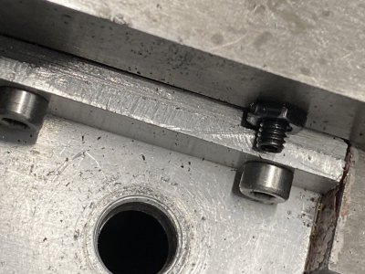
That is why I moved mine. The SIEG lock is designed to be mounted on the chuck side of the carriage to take advantage of the existing tapped holes (for the travel rest) and because of interference with the gib adjusting screws. I tried that, didn't like the big handle so changed that to a smaller one, still didn't like it so modified the lock and drilled & tapped holes on the tail stock side of the Carriage per the link in Post #5. However, I really like your solution and will probably adapt my locking screw to work with his attachment point the next time I have the Saddle removed (or I may just take the tail stock off, run the Saddle all the way to the right and drill & tap the mounting holes in place).Can someone explain why they prefer the carriage lock to be on the left side of the carriage? It would seem to be far more logical to put it on the right side away from the chuck so the carriage can be locked without turning off the lathe.
What am I missing here?
What material did you use for the angle? It has a tight inside corner so I assume you fabricated it from steel?Could you drill & tap the other side of the carriage so it would be away from the rotating chuck.
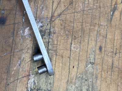
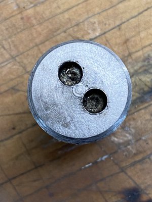
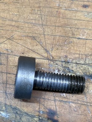
Here is what I made to lock my carriage. It works quite well. I made oiler fittings for the existing holes in the carriage.
Charlie