

- Joined
- Dec 22, 2020
- Messages
- 97
First, let's identify the victim.

This is an early MK II with the cast iron headstock. Current upgrades are the headstock bearings, Metal gibs for the cross and compound, Phase II QCTH, and a thorough cleaning that uncovered a few common ills that were fixed.

My current boggle is .5mm pitch threads.
So I have acquired a drawing describing the extension bracket and 3D printing is in progress on two fronts. The first is an 80% in-fill for immediate experiment/use and the second is for 15% in-fill for lost PLA casting. Seems that any less than 15% in-fill risks dimensional stability. @wa5cab I hesitate to post my drawing or code to avoid any confusion after reading some previous posts.
Now the issue is how and where/when to use it. "Do the file "Atlas M6-735 Instructions For EXT BRKT For MM Threads.pdf" strike a familiar note"?
So today with some time on my hands I'll attempt to CAD/Code the part for my router and see if I can mill it out when I get back to the shop.
As for the bracket , M6-25M the drawing I have is dated 2-23-38 and probably has nothing to do with the later 041-464 change gear bracket from the Mk II . In any case the bracket will get drawn , coded , built , and added to the library for what ever reason. Most likely for my brother's 618 and any others that can benefit.
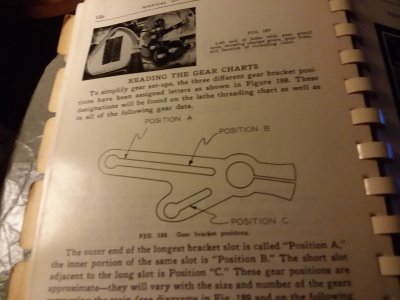
For .5mm pitch the 54 on the screw is easy enough. B for back position. Position "C" again is easy enough 44B and 46F. Now without the bracket here to play with it gets a bit curious. "A" is the position furthest from the screw and 36B , 20F. Position "B"is the source of confusion. As I understand it position "B" is between the screw and position "A". The 20B and 40F designation are no problem but I for the moment I fail to see how it all fits together. I suppose It will have to wait for me to be sitting in front of the machine.
In advance, Thank You all for your efforts here. If there is any way anyone can help clarify this it would be appreciated.
~kop
This is an early MK II with the cast iron headstock. Current upgrades are the headstock bearings, Metal gibs for the cross and compound, Phase II QCTH, and a thorough cleaning that uncovered a few common ills that were fixed.
My current boggle is .5mm pitch threads.
So I have acquired a drawing describing the extension bracket and 3D printing is in progress on two fronts. The first is an 80% in-fill for immediate experiment/use and the second is for 15% in-fill for lost PLA casting. Seems that any less than 15% in-fill risks dimensional stability. @wa5cab I hesitate to post my drawing or code to avoid any confusion after reading some previous posts.
Now the issue is how and where/when to use it. "Do the file "Atlas M6-735 Instructions For EXT BRKT For MM Threads.pdf" strike a familiar note"?
So today with some time on my hands I'll attempt to CAD/Code the part for my router and see if I can mill it out when I get back to the shop.
As for the bracket , M6-25M the drawing I have is dated 2-23-38 and probably has nothing to do with the later 041-464 change gear bracket from the Mk II . In any case the bracket will get drawn , coded , built , and added to the library for what ever reason. Most likely for my brother's 618 and any others that can benefit.
For .5mm pitch the 54 on the screw is easy enough. B for back position. Position "C" again is easy enough 44B and 46F. Now without the bracket here to play with it gets a bit curious. "A" is the position furthest from the screw and 36B , 20F. Position "B"is the source of confusion. As I understand it position "B" is between the screw and position "A". The 20B and 40F designation are no problem but I for the moment I fail to see how it all fits together. I suppose It will have to wait for me to be sitting in front of the machine.
In advance, Thank You all for your efforts here. If there is any way anyone can help clarify this it would be appreciated.
~kop
")