Knurl Tool Project (clamp type)

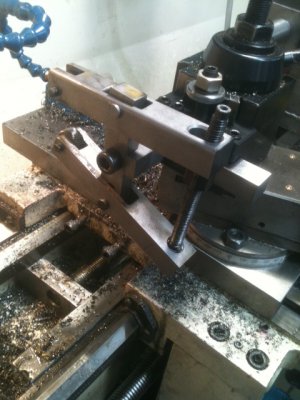
Here's the latest CAD design. It's "ambidextrous" and can be flipped over or used on either side of the tool post.

Remember: If you download it and open it with genuine Adobe (most PDF clones won't work properly) and click the image, you can rotate in all dimensions by pressing the left click and scrolling your mouse wheel or touchpad.

I'll ZIP together a more complicated set of drawings that shows the pin diameters and lengths. They're left out of the PDF image because it makes it easier to view. Also, won't specify the clamp bar width or the center bolt diameter as some folks may want this for varying sizes of tool holders.

If you're interested in dimensions, send a private message...

3D Knurl Tool Attachment: View attachment KnurlTool.pdf

Ray
 
Here's the latest CAD design. It's "ambidextrous" and can be flipped over or used on either side of the tool post.

Remember: If you download it and open it with genuine Adobe (most PDF clones won't work properly) and click the image, you can rotate in all dimensions by pressing the left click and scrolling your mouse wheel or touchpad.

I'll ZIP together a more complicated set of drawings that shows the pin diameters and lengths. They're left out of the PDF image because it makes it easier to view. Also, won't specify the clamp bar width or the center bolt diameter as some folks may want this for varying sizes of tool holders.

If you're interested in dimensions, send a private message...

3D Knurl Tool Attachment: View attachment 62407

Ray

Hey Ray,

What CAD program do you use? That pdf is neat!

Duncan
 
Hi Duncan...

If you look at post #9 in this thread, the CAD program is mentioned. It's nice and I like it. It has an Assembly function that allows you to move all the parts as though they were real and you can measure and verify all the ranges of motion. It would be cool if the PDF allowed that too but, it doesn't...

Ray

Thanks Ray - I should have read the thread more carefully :banghead:
 
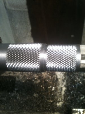
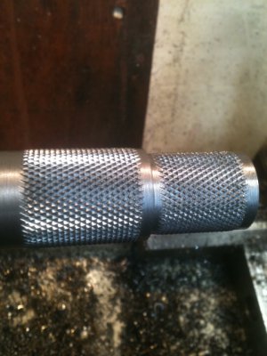
It works well... If you get the convex knurl wheels from Accutrak, it seems the best method is to position them and swiftly apply pressure until it forms the knurl properly. Don't be afraid to stop the machine to check for a nice diamond pattern. Apply more pressure until the patter is correct. Then, engage the autofeed and cut the desired length. Just make one pass. Keep it soaked with cutting oil. I use the slowest possible feed rate on the machine. The leading convex edge on the wheels do a nice job of slowly forming the pattern. This piece was spun at about 60 RPM. It's about 1" diameter -soft metal. These were the 1st two knurls cut with the new tool.

Finally, don't put anything (like your fingers) near those rollers. Anything and everything that gets caught in those wheels will get destroyed.

KN1.JPGKN2.JPGKN3.JPG

Ray

KN1.JPG KN2.JPG KN3.JPG
 
Last edited:
Wow great Ray!
This is near the top of my project list- as I have some knurling to do.

I do have a question- if you think it is OT then I can start a new topic with it- but I wouldn't have known that a knurling could be fed? (I know nothing about knurling)... I would have thought it would require cutting the knurl, and then moving down to the next open section. Thinking more about this, I guess it would make for obvious misalignments of each knurl cut that way though.
Is carriage feeding the knurl the normal method for this?

Bernie
 
Looking really nice! I would love to check out that draw it on the computer and move the pieces around like they were real. Sounds great for a guy who can't always picture 3d from a 2d drawing. By the way, how's the finger coming along?
 
Great looking tool Ray, and it seems to work brilliantly. Bernie, I have stopped trying to figure this one out in my head but you can hand feed the carriage when knurling and it still comes out great?

Thanks Shawn-

It doesn't seem like it should work, like the last row of knurls would start to be chewed up as the carriage moved along. I am sure not arguing! I have to make a clamp style like this. I have tried the old-push style and it cam out like crap! Maybe I'm not feeding hard enough.

Didn't someone post a table of the TPI for knurl-wheel/diameter of work recently? Where did I see that?


Bernie
 
Some replies to the last couple posts but first, I do not claim to be a knurling expert so take it all with a grain of salt...

My old knurl tools were junk. One was the "push-in" type that are out of vogue and obsolete. My other unit was a scissor type (like a heavy duty pair of pliers) but, it had all kinds of wiggle and slack in the mechanism -too much trouble to repair. I think a proper set of those in good condition would work just as well as this clamp type.

The design goal was to eliminate as much slop and wiggle as possible so the arms do not change angle once the carriage is moved. Also, I wanted really hard/tough metal so the tolerances stand a chance of longevity as the tool is used. I was only going to make it RC 40 but while it was cooking in the oven, I decided to make it RC 50.

The wheels are convex on the edges which provides a gradual lead-in of the cut as the carriage moves. The edge does all the hard work. Please go to the accutrak website and look at the convex wheel so you can see what I'm talking about.

I mentioned "swiftly establish the starting pattern" for a reason. A knurled rod must have a diameter that falls on a proper multiple of the diameter of the wheels (which is directly related to the pitch for a given wheel). There's a little formula to calculate this. When you first start establishing the pattern, the teeth are not sunk-in far enough to make a full cut and during this time, the effective diameter of the wheel does not meet the needs to allow an integer multiple of tooth cuts to wrap properly around the shaft. If you spend too much time getting the starting pattern established, all you'll do is obliterate the surface of the shaft. I tried to get the pattern established in about 10 full turns of the shaft. In the future, I'll see if I can do it faster than that.

I use the feedrod for consistency. The feed is very slow. At 60 RPM, it took several minutes (5 minutes?) to cut each of those 1.25" length segments. As it cut, I dribbled a little dark oil on there to help flush out the crumbs. Letting the crumbs pack-up will kill the knurl. --- I can't emphasize enough, do not get your fingers caught in that pinch roller. The top roller tries to pull you in. ---

The drawings... For some reason, the 2D drawings are coming out HUGE when converted to PDF. That's why I didn't post them. I'm still looking at options and settings to reduce the size.

The fingers. They're much better; I'm back in the saddle and they don't require such care as they did before. The wounds have all healed except on one where there's still a scab and thick patch of skin that's slowly peeling off. They look fine and are not deformed -just an extra contour on one of them. The tips are almost completely numb -I'd say, 60-80% depending on which finger. The location of the scar is extremely sensitive as it seems the nerves are re-growing. Touching certain areas feels like an electric shock. -This is a normal and predictable side-effect. The numbness has an advantage. When I have to pick up something kinda hot, I use those fingers :). (For those of you who don't know, I badly lacerated 3 fingers on a heavy, sharp piece of metal. No, I didn't get them caught in a knurl tool).

Here's a copy of that spread sheet for knurl pitches... Two formats: One for Old Excel and one for New Excel.


Ray

View attachment KnurlPitchDiameters972003XLS.xls
View attachment KnurlPitchDiameters.xlsx
 
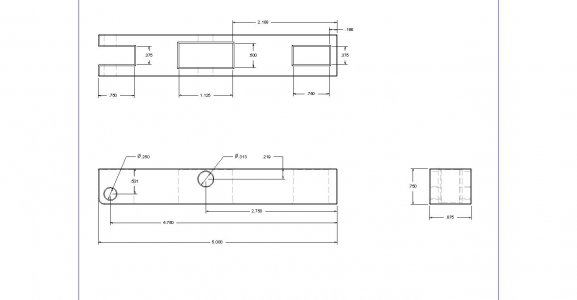
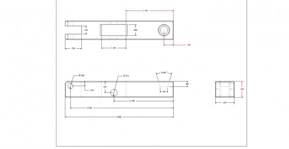
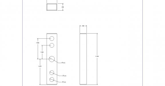
I guess better late than never... I forgot to post the drawings. Here are the main components. I did not show the pins, the threaded rod and nut for tension or, the angle bracket to connect to your QCTP. Those things are either obvious or, specific to the size of your QCTP.

Here you go...


KnurlTopBar.jpgKnurlBottomBar.jpgVerticalBar.jpg


Enjoy...


Ray

KnurlBottomBar.jpg KnurlTopBar.jpg VerticalBar.jpg
 
Back
Top