- Joined
- Nov 16, 2012
- Messages
- 5,596
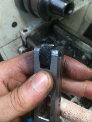
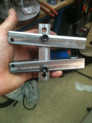
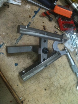
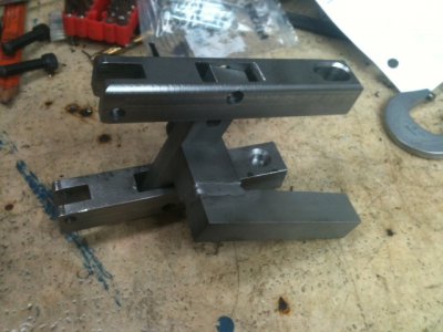
Finally getting around to making a decent knurling tool; precipitated by the fact that next week I've got a job that needs knurling. All the knurl tools I have are somewhat sloppy and loose fitting -and that makes knurls look terrible because the rollers need to travel in a perfect axial line with the stock. When there's slack in the arms or rollers, they go off line. I'll be on my best behavior and make this thing very close fitting, hopefully with no noticeable slop.
So, in a fit of boredom, I drew up these plans. -Nothing special and it's an old design. Once I make this thing and if the design works well, I'll publish the dimensions. It has two ranges from very small up to 1.125" and a second range up to 2.25". Honestly, I've never knurled anything much over an inch if memory serves...
The large pieces will be made of 4150 (drops laying around) and heat treated to RC 45 or so. All the pivot pins are going to be made of 4340 -which is considered a "super alloy" that's both hard and tough. I had to order that material and it hasn't arrived yet. Knurl pins need to be very hard and a super close fit. There's a lot of pressure on them and if any swarf gets in there, it will grind soft metal to a pulp. Also, precision fit is needed to keep the wheels from wiggling. A grade 8 bolt stuffed in there wouldn't stand a candle's chance in a windstorm..
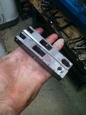
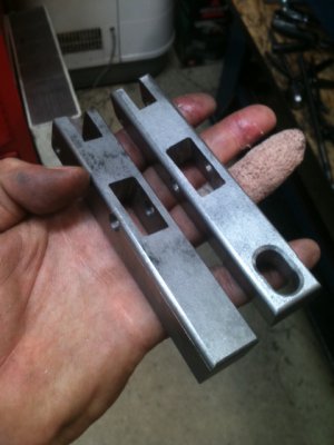
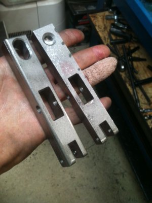
So far, I've carved down all the big pieces to final size and soon we'll drill the holes and do more milling. I've been using carbide roughing endmills lately and on the pieces shown, I shaved of 0.25" with fingertip pressure on the table cranks in just a few moments... (hint hint, consider saving your pennies and trying them out).
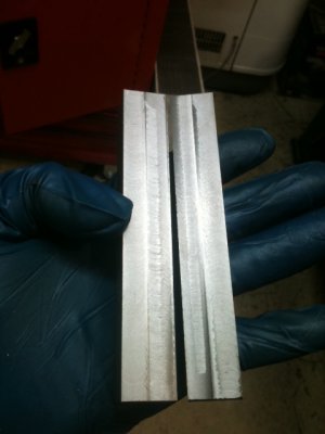
Here's a PDF of the tool. Once you download it, you can click the image and Adobe Reader will allow you to use the mouse buttons to rotate and see different angles. Also, here's an obligatory eye-candy picture of some metal fresh out of the mill.
Knurl Tool PDF: View attachment KnurlTool.pdf
Ray

So, in a fit of boredom, I drew up these plans. -Nothing special and it's an old design. Once I make this thing and if the design works well, I'll publish the dimensions. It has two ranges from very small up to 1.125" and a second range up to 2.25". Honestly, I've never knurled anything much over an inch if memory serves...
The large pieces will be made of 4150 (drops laying around) and heat treated to RC 45 or so. All the pivot pins are going to be made of 4340 -which is considered a "super alloy" that's both hard and tough. I had to order that material and it hasn't arrived yet. Knurl pins need to be very hard and a super close fit. There's a lot of pressure on them and if any swarf gets in there, it will grind soft metal to a pulp. Also, precision fit is needed to keep the wheels from wiggling. A grade 8 bolt stuffed in there wouldn't stand a candle's chance in a windstorm..
So far, I've carved down all the big pieces to final size and soon we'll drill the holes and do more milling. I've been using carbide roughing endmills lately and on the pieces shown, I shaved of 0.25" with fingertip pressure on the table cranks in just a few moments... (hint hint, consider saving your pennies and trying them out).
Here's a PDF of the tool. Once you download it, you can click the image and Adobe Reader will allow you to use the mouse buttons to rotate and see different angles. Also, here's an obligatory eye-candy picture of some metal fresh out of the mill.

Knurl Tool PDF: View attachment KnurlTool.pdf
Ray


