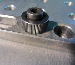
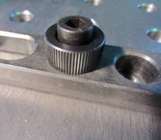
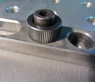
Is It Possible To Make One Of These?

little_sparky

Active User
Registered
Joined
Dec 9, 2014
Messages
59
Hello all,

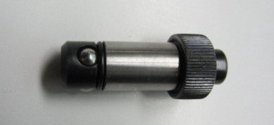
I have a thread on making a build pro welding table, it is linked at the bottom, and i am wondering if it is possible to make the ball lock bolts that are used with the table? They screw on and when tightened the balls push out at bottom, gripping to the underside of the table, but i don't know exactly how this is done, whether a plate pushes the balls out or what. They can be bought in a 10 pack for around about $250, so $25 a piece, if it takes any longer than 2 hours to build each one than its probably not worth it. any input would be greatly appreciated.

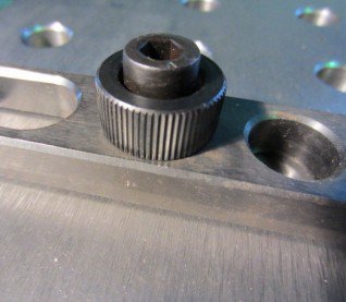
here is the bolt:
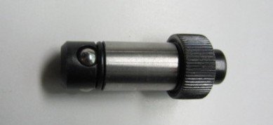
Ball_Lock_Bolts_VT65010_72_1_20131021175433.jpg

and link to the table:
http://weldingweb.com/showthread.php?574411-Buildpro-inspired-Welding-table-(question)

cheers
little_sparky
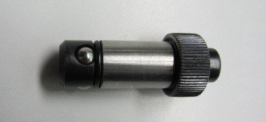
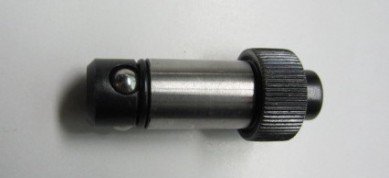
Ball_Lock_Bolts_VT65010_72_1_20131021175433.jpg

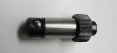
Ball_Lock_Bolts_VT65010_72_1_20131021175433.jpg

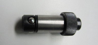
Ball_Lock_Bolts_VT65010_72_1_20131021175433.jpg

Ball_Lock_Bolts_VT65010_72_1_20131021175433.jpg

Ball_Lock_Bolts_VT65010_72_1_20131021175433.jpg
 
the balls will be forced out by a cone and kept from falling out of the hole by means of the o ring
making 10 in 20 hours time should be doable if you figure out the exact dimensions first
 
oh yeah i get exactly what your saying, i would never have guessed that, but it makes so much sense.

understanding it is one thing, knowing how to build it is another, and having the tools to do so is crucial haha.
i have a lathe so i should be able to nut most of it out, the bit that has me stuck is how im going to drill a perfect size hole for the small balls at the right angle. :concerned:
 
Anything is possible! ;)
Although, as you say it comes down to knowledge, tools and cost......but also more. Somethings may be cheaper to buy, but more fun to make. It depends how you value your time in your shop.

There may also be a simpler way to get roughly the same function.
Several folks here have added a hand-crank to their lathe spindle for things like threading up to a shoulder, special indexing jobs, etc.
I'll need to dig around a bit to find a link, but their expandable shaft is built like a wedge.

It is also used on some bench clamps like this:
http://www.leevalley.com/en/wood/page.aspx?p=59754&cat=1,41637,59754
http://www.leevalley.com/en/wood/page.aspx?p=59756&cat=1,41637
When you tighten the stud the two angled faces get pulled together and slide making their effective diameter larger. The part gets locked into the hole.
The trick is having an oversized hole in one of the parts for the thru bolt, because it has to move side-ways.

-brino
 
I have not used those particular clamps before, but I have used others that might be similar.
If I am looking at the picture right, they appear to be about the same as the ones I have used. Sadly the link does not provide any information relevant to the clamp. A link to the item pictured would be far more useful.

Assuming I am looking at everything correctly:
They do not clamp under the table, they clamp the bore. When you tighten it, the balls are forced out and push against the walls of the bore.
The o-ring is not used to retain/retract the balls. The o-ring provides a small bit of friction so the clamp will tighten and not just spin in the hole.
The balls are retained by staking around the top of the hole (I might be mistaken on this).
The balls are forced out by a tapered plunger.
The bore for the balls is probably at 90*.
The balls retract by just loosening the nut, they will passively release.

If you think through the 4 different things that must happen with the balls, you will see that 90* is probably the best angle for the hole in most situations.
You have to be able to put the clamp in and not have the balls drag, so the hole angle can't be toward the top.
You have to be able to force the balls out so they do not push the clamp up, so the angle can't be toward the bottom.
You have to be able to release the balls by pulling out the clamp, so the angle can't be toward the bottom.
You have to be able to remove the clamp, so the angle can't be toward the bottom.

The holes need to be very smooth for good operation, so just drill and ream them. This could be done on a drill press, but a mill is probably a better option for the added rigidity.

With a bit of forethought, you should be able to make all the threads standard sizes so taps and dies can be used.

The only difficult part will be staking the holes so the balls don't fall out. I supposed the o-ring could be used to retain the balls, but they will get lost when the o-ring eventually breaks. You should be able to make a staking fixture from a C-shaped piece of steel and some drill rod, and use it in the arbor press.

EDIT: I downloaded the image and zoomed in on the ball. The more I look at it, the more it looks like the o-ring does retain the balls. Maybe the clamp is made from something that does not swage well enough to stake the holes, or it was just a design compromise to keep price down.
 
Last edited:
oh yeah i get exactly what your saying, i would never have guessed that, but it makes so much sense.

understanding it is one thing, knowing how to build it is another, and having the tools to do so is crucial haha.
i have a lathe so i should be able to nut most of it out, the bit that has me stuck is how im going to drill a perfect size hole for the small balls at the right angle. :concerned:

The holes probably to small for the balls to fall out. I would guess you put them into the hole the cone piece and tightening knob threads into. Probably dosn't need to be very accurate (just not to big) :)

Stuart
 
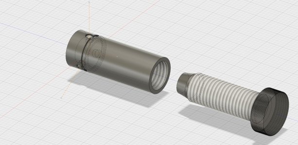
screw clamp v1.jpg I needed some practice with using primitive solids in Fusion 360 anyway lol
It would probable be easier to make with 4 balls rather than 3 so you could just cross drill all the way through and rotate 90* and repeat.
This worked out pretty well dimensionally. The balls are 2mm, the body is 10mm. the threaded section is 8mm x 1.0mm, and the knurl is 12mm. The plunger is 7mm giving 0.5mm of ball travel. It will clamp a hole up to just under 11mm in diameter, though a 10mm hole is the nominal size.
 
You say they screw on? It would be a very poor design if the balls are held in with the O ring. You would be losing balls like crazy. I think the edge of the hole is swedged to retain the balls. The O ring is just to keep everything in place when in the hole. And a spring loaded button on top to retract the balls…Dave
 
Last edited:
Sadly the link does not provide any information relevant to the clamp. A link to the item pictured would be far more useful.
Sorry about that, this new link doesnt provide much more information but here it is.
http://www.weldingtables.com.au/product/ball-lock-bolts
They do not clamp under the table, they clamp the bore. When you tighten it, the balls are forced out and push against the walls of the bore.
if you click on the link it says that they lock under the table. I too thought that it would make more sense to grab onto the walls of the hole but then i thought that becuase the table is only 5/8" thick they need to use as much of the hole as possible and gripping under the table would provide just that extra bit of rigidity.

View attachment 119175 I needed some practice with using primitive solids in Fusion 360 anyway lol
It would probable be easier to make with 4 balls rather than 3 so you could just cross drill all the way through and rotate 90* and repeat.
This worked out pretty well dimensionally. The balls are 2mm, the body is 10mm. the threaded section is 8mm x 1.0mm, and the knurl is 12mm. The plunger is 7mm giving 0.5mm of ball travel. It will clamp a hole up to just under 11mm in diameter, though a 10mm hole is the nominal size.
Wow, nice work on the solids, i had a go at it last night on google sketchup but had the cone the wrong way, i dont know what i was thinking haha, this picture puts everyones words, including your own, into an image, love it, thanks heaps.
 
Ball_Lock_Bolts_VT65016_75_1.jpg
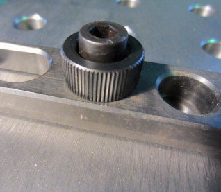
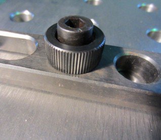
looking at this image, it's as though the knurl is independant from the hex bolt head and when i have watched videos they turn the knurled part to lightly tighten the bolt and then use the hex head to really tighten it.

How would this work? does this suggest that the knurled part has a thread in the centre of it aswell? if it does i dont see why the two can't just be a single peice of steel?
Possibly to keep costs down again?

Ball_Lock_Bolts_VT65016_75_1.jpg

Ball_Lock_Bolts_VT65016_75_1.jpg

Ball_Lock_Bolts_VT65016_75_1.jpg

Ball_Lock_Bolts_VT65016_75_1.jpg

Ball_Lock_Bolts_VT65016_75_1.jpg
 
Back
Top