Installing Igaging Absolute DRO's on 1953 SB 9A

yota

Registered
Registered
Joined
Jul 14, 2021
Messages
443
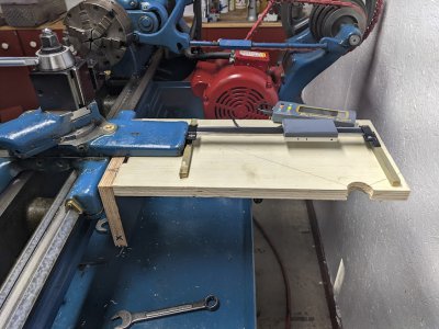
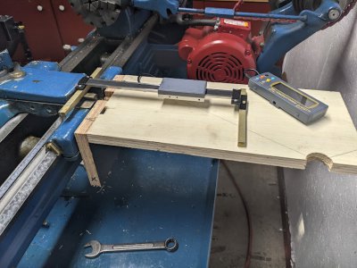
if you have an old SB9 you know that the cross feed DRO install can be a challenge due to the shape of the carriage and cross feed and the low profile design. this is my take on a vid I saw on youtube. I mocked this up in wood for now to make decisions. looking for input/suggestions. note that this unit would fit atop the carriage next to the cross slide but A. it would block access to the gib screws, B. it would make access to the compound lock screws more of a pain than they already are :). C. and maybe most important I would no longer be able to use the follow rest as the mount would be blocked off.

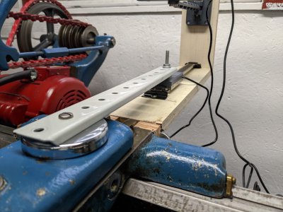
Ist pic is with cross slide all the way forward. the scale will be attached to the cross slide with a small bolt. the other end will glide on the soon to be aluminum fixed plate with a small pc of teflon screwed under it. a bracket screwed to the soon to be aluminum fixed plate will hold the read head stationary. the plywood plate is 7" wide but the alum one will be 6" wide. has to be that width minimum to use the 2 threaded holes in the end of the carriage.
k.jpg
 
Last edited:
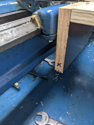
pic with cross slide 6" to the rear (limit of travel).

kk.jpg
 
vertical piece will support the read head for the DRO on the longitudinal axis. may be able to shorten it.

kkk.jpg
 
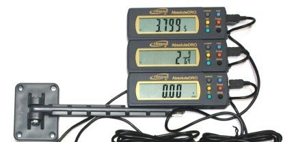
oh, that big aluminum table will also hold a mount fabricated to stack the 2 read-outs like this.

wpeca89ad3_05_06__83708.1534339167.jpg
 
Nice plan. Seems like the plate supporting the far end of the cross-slide scale could narrow in width toward its distal end.
 
That's a lot hanging out in mid air. Check out DRO Pros web site for pictures of installations on lathes like yours. They have a lot of good general information that will apply to any DRO. I will copy something that someone else has figured out that works. A South Bend is one of the most common lathes out there. There should be lots of installations that can provide ideas. Do a search on this web site also. It should also provide more ideas. Good luck and please show us some pictures of your final installation. We love pictures.
 
Nice plan. Seems like the plate supporting the far end of the cross-slide scale could narrow in width toward its distal end.
got me thinking. just because the vertical plate needs to be 6" wide to catch the 2 bolt holes doesn't mean that the horizontal plate needs to be the same width.
 
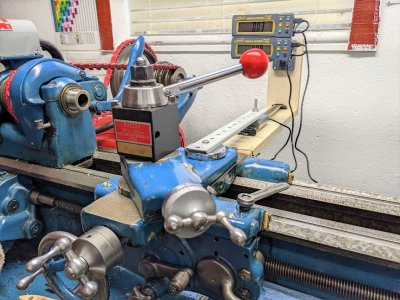
re-thought this today. previous plan had the scale attached to the cross slide and moving back and forth with the read head fixed to the plate. decided to reverse this and fasten the scale to the plate and have the read head move back and forth with the cross slide. also cut the horizontal plate down to 3 1/2". added a vertical riser on the back of the plate to hold the displays. instead of drilling holes in the cross slide I used a powerful magnet to hold the end of the bracket to the read head. I think I'm also going to use magnets to mount the Z axis scale to the back of the bed instead of drilling holes in the cast iron. this is now a fully working mock up.

bbbbbbbb.jpgbbbbbb.jpg
 
I like the idea that the displays move with the carriage and are always in front of my face.
 
I like the idea that the displays move with the carriage and are always in front of my face.

That does seem good. In the metal one, I’d put a gusset on it to stiffen the horizontal.
 
Back
Top