- Joined
- Dec 18, 2019
- Messages
- 6,447
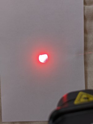
Just got my Neiko tach. Was excited when it arrived. This looks more like a cheap kit than anything, but it mostly works. The battery springs are in full coil bind and then some. The supplied batteries wouldn't fit. Had to find some other batteries that would fit. The laser spot is not aligned correctly and is internally occluded. The spot is uneven in illumination within the beam and sharply cut off due to the misalignment. The battery compartment screw was installed by Godzilla. Have no idea why it was screwed in so tightly! This photo is overexposed, the illumination is worse than this. Camera is making it look better than it is.

But, it does seem to work. I cleaned my chuck with alcohol wipes and wrapped a piece of black electrical tape around it, leaving a shiny gap about one beamwidth. It is concerning that if I move the tach a little to the right, the readings are much different. My chuck is still slinging a little oil, so I get a couple of droplets on the tach. Kind of annoying, and undoubtedly not so hot for the "optics".
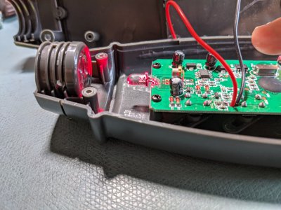
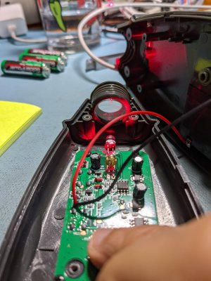
Trying to decide if I will return it, or open it up and try to fix it. The packaging that this unit came in is totally ineffective against a product drop. It might have left the factory ok, (optically), but there really was nothing to help cushion any common carrier shipping. This is a typical Amazon thing. They probably made a cost tradeoff between shipping damage and good packing and chose shipping damage.


