INCH CHART BY 128ths

A long time ago I realized that a good drawing should not require the machinist to grab his calculator any more than absolutely necessary. It simply gives him another chance to screw up make a mistake. Since the machines in the U.S. are graduated in decimal inches, with the exception of threads, my drawings have metric dimensions translated to and toleranced in decimal inches. I don't use fractions, two place and three place decimals (±.010 and±.005) are loose enough. The metric system of tolerancing makes me nuts, WTH is H6 tolerance for a 30mm shaft? You have to refer to a chart instead of having the actual numbers on the drawing, which just introduces another opportunity for error. I'm sure in some way it makes sense and possibly simplifies the job for the draftsman, but it doesn't make life easier for the machinist or the inspector. Look at the drawing after the parts are done, the machinist's notes will tell you if it needs to be revised.
Most machinists have a laminated small Zeus book or similar in their toolbox that has a limits and fits page for hole and shaft tolerances.
Here is a link - https://www.arceurotrade.co.uk/Catalogue/Books/ZEUS-Precision-Reference-Tables
When I trained in a drawing office I was told that I had to do all the calculations because I had a clean space to work in and a machinist does not.
I never used fractions except when a part was left stock size, even then I would write e.g. 1/2" STOCK this was to ensure the machinist did not waste any time machining that dimension.
 
A long time ago I realized that a good drawing should not require the machinist to grab his calculator any more than absolutely necessary. It simply gives him another chance to screw up make a mistake. Since the machines in the U.S. are graduated in decimal inches, with the exception of threads, my drawings have metric dimensions translated to and toleranced in decimal inches. I don't use fractions, two place and three place decimals (±.010 and±.005) are loose enough. The metric system of tolerancing makes me nuts, WTH is H6 tolerance for a 30mm shaft? You have to refer to a chart instead of having the actual numbers on the drawing, which just introduces another opportunity for error. I'm sure in some way it makes sense and possibly simplifies the job for the draftsman, but it doesn't make life easier for the machinist or the inspector. Look at the drawing after the parts are done, the machinist's notes will tell you if it needs to be revised.
I agree that all of the necessary information should be included on the drawing, but in these times with almost all machines being equipped with DRO's, having a mix of inches & mm should not be an issue, particularly for the hobby machinist.

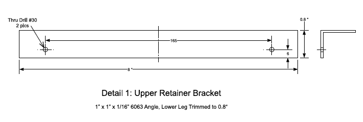
Most of my designs are for my own use, so I use the appropriate unit of measurement for the job at hand. For example (from a forthcoming article for hobby machinists):

Retainer.png

• The stock is 1" x 1"x 1/16", because that how it is manufactured.

• The angle is cut to a length of 8" and one leg of the angle is "trimmed" to 0.8" (neither are super-critical dimensions).

• The holes are #30 (clearance for M3, but not everyone has a 3.3mm bit while most will have a set of numbered bits).

• The holes need to be 165mm +/- C-C (to match existing holes in a metric machine, a much better dimension than 6.496").

• Since whoever is making this bracket is most likely laying out/locating the holes with a DRO, it makes sense to locate them 6mm (rather than 0.236") from the edge of the angle.

If starting with a lump of material, all of the dimensions would be in the same units, and is this case millimeters since the part needs to fit on an existing "metric" machine.

I grew up with inches & feet, transitioning to meters & millimeters (and all of the SI units), but my career involved macro dimensions (multiple feet/yards/miles/kilometers) rather than micro dimensions (inches/centimeters): my involvement with thousandths of inches and hundredths of mm's came mostly as I approached retirement, and then for hobby-level work.
 
I agree that all of the necessary information should be included on the drawing, but in these times with almost all machines being equipped with DRO's, having a mix of inches & mm should not be an issue, particularly for the hobby machinist.

Most of my designs are for my own use, so I use the appropriate unit of measurement for the job at hand. For example (from a forthcoming article for hobby machinists):

View attachment 418519

• The stock is 1" x 1"x 1/16", because that how it is manufactured.

• The angle is cut to a length of 8" and one leg of the angle is "trimmed" to 0.8" (neither are super-critical dimensions).

• The holes are #30 (clearance for M3, but not everyone has a 3.3mm bit while most will have a set of numbered bits).

• The holes need to be 165mm +/- C-C (to match existing holes in a metric machine, a much better dimension than 6.496").

• Since whoever is making this bracket is most likely laying out/locating the holes with a DRO, it makes sense to locate them 6mm (rather than 0.236") from the edge of the angle.

If starting with a lump of material, all of the dimensions would be in the same units, and is this case millimeters since the part needs to fit on an existing "metric" machine.

I grew up with inches & feet, transitioning to meters & millimeters (and all of the SI units), but my career involved macro dimensions (multiple feet/yards/miles/kilometers) rather than micro dimensions (inches/centimeters): my involvement with thousandths of inches and hundredths of mm's came mostly as I approached retirement, and then for hobby-level work.
This seems like a metric part that has been converted to imperial where possible. The imperial stock size is unavoidable.
If the 0.8" & 8" dimensions are relatively unimportant then could they be changed to 20mm & 200mm. This would make the drawing simpler to calculate the distance of the holes from the ends ( assuming they are equal about the centreline ). All the dimensions would then be in the same units except the hole diameters. Instead of using another measurement system ie the number drills, could you use 1/8" drill instead.
Holding a part like this usually has the long leg against the fixed jaw for machining the short leg and the holes, could the hole dimension be from the other side i.e. 14mm. If the 0.8" is not important then perhaps the dimension from the long leg may be the important dimension, they often are if the part is sitting on the long leg.
 
Back
Top