-
Welcome back Guest! Did you know you can mentor other members here at H-M? If not, please check out our Relaunch of Hobby Machinist Mentoring Program!
You are using an out of date browser. It may not display this or other websites correctly.
You should upgrade or use an alternative browser.
You should upgrade or use an alternative browser.
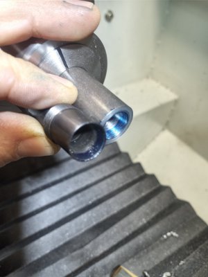
High sped quill using die grider collet
- Thread starter BCwoods
- Start date
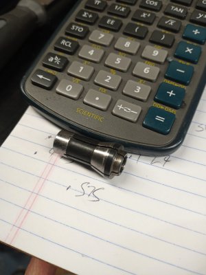
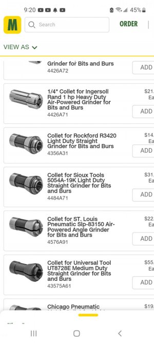
Yes I took this off a Harbor freight die grinder. This accepts 1/4 shanks. However all I can find is what mcmaster Carr calls air powered bit and burr grinders. These are pretty standard from what I can find. Just no technical info
Attachments
- Joined
- Nov 24, 2014
- Messages
- 3,179
The next steps depend on what you have to work with.
Do you have a lathe with a decent 4 jaw independent chuck?
Does your lathe have a compound slide?
Do you have a .0001" reading DTI?
FYI, in the future, doing as described in the linked thread can get the necessary info more quickly.
 www.hobby-machinist.com
Do you have a lathe with a decent 4 jaw independent chuck?
Does your lathe have a compound slide?
Do you have a .0001" reading DTI?
FYI, in the future, doing as described in the linked thread can get the necessary info more quickly.
[How-To] - Ask a Better Question
Asking better questions will get you better replies. By asking a question, you're asking others to do some work for your benefit. Please put in the effort to ask a better question so the replies can be more focused, useful to your issue and show respect for the contributors. A good question...
www.hobby-machinist.com
Last edited:
Hi yes hello. Point taken and your right. I guess I thought these types of collet that are in every for grinder I have seen would be more known then not. Ok I have a pm1440gt so it has what you are asked. I belive you are saying sweep the receiver part of the taper holder and use some trig? There is a dro on the machine in the x axis.
- Joined
- Nov 24, 2014
- Messages
- 3,179
Very good, here we go.
The Hard part, IMO, is to set the compound properly to cut the correct taper.
Here's what I think I would do if I were in your shoes.
I would use the female taper (in the collet chuck) as a Master Reference (assuming it's in good shape).
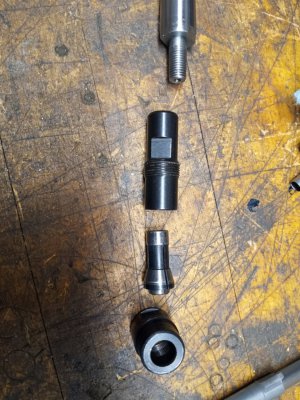
I would hold a piece of bar stock in the 4 jaw chuck. Rough it to your best guess taper angle and turning the cylindrical portion (like the small end of the collet). In other words, the workpiece is going to look like a collet (without slots) on the end of the bar stock.
Start with the bar stock out far enough from the jaws so you can keep nibbling if the angle isn't perfect at first.
Don't forget to shorten the cylindrical end if more attempts at the taper leave the cylinder too long.
Make your finish cut using the boring bar/holder (we'll call it the Finish Bar/Holder) you will use to finish the female taper in the tool spindle.
To do that you will have to do the finish cut running the spindle in reverse and cutting on the far side of the workpiece.
That is because the angle of the taper, that the boring bar cuts, is dependent on the height of the cutter relative to the workpiece axis.
By using the same tool/holder to cut both the male (bar stock/test piece) and female tapers, they should match.
After you have replicated the collet taper and cylinder, Blue (Hi-pot Blue, not layout fluid) the female features in the collet chuck and carefully print the test piece taper.
If the test piece taper prints at the big end only (ring), you need to turn the compound (cutter end) toward the operator.
If the test piece prints at the small end only (ring), you need to turn the compound (cutter end) away from the operator.
Use a DTI against an edge of the compound to know how much you are are adjusting the angle.
When the test piece prints nicely in the Master (collet chuck), your compound is set to the right angle.
Take the bar stock (test taper) out and take great care to center the spindle in the 4 jaw.
Use other cutters/holders to rough in the female features (normal forward lathe rotation) in order to minimize wear on the Finish Bar/Holder.
If the cutting edge height of the Finish Bar/Holder changes, it will cut a different taper so take it easy on the Finish Bar/Holder.
I think I got that right. What do you think?
The Hard part, IMO, is to set the compound properly to cut the correct taper.
Here's what I think I would do if I were in your shoes.
I would use the female taper (in the collet chuck) as a Master Reference (assuming it's in good shape).
I would hold a piece of bar stock in the 4 jaw chuck. Rough it to your best guess taper angle and turning the cylindrical portion (like the small end of the collet). In other words, the workpiece is going to look like a collet (without slots) on the end of the bar stock.
Start with the bar stock out far enough from the jaws so you can keep nibbling if the angle isn't perfect at first.
Don't forget to shorten the cylindrical end if more attempts at the taper leave the cylinder too long.
Make your finish cut using the boring bar/holder (we'll call it the Finish Bar/Holder) you will use to finish the female taper in the tool spindle.
To do that you will have to do the finish cut running the spindle in reverse and cutting on the far side of the workpiece.
That is because the angle of the taper, that the boring bar cuts, is dependent on the height of the cutter relative to the workpiece axis.
By using the same tool/holder to cut both the male (bar stock/test piece) and female tapers, they should match.
After you have replicated the collet taper and cylinder, Blue (Hi-pot Blue, not layout fluid) the female features in the collet chuck and carefully print the test piece taper.
If the test piece taper prints at the big end only (ring), you need to turn the compound (cutter end) toward the operator.
If the test piece prints at the small end only (ring), you need to turn the compound (cutter end) away from the operator.
Use a DTI against an edge of the compound to know how much you are are adjusting the angle.
When the test piece prints nicely in the Master (collet chuck), your compound is set to the right angle.
Take the bar stock (test taper) out and take great care to center the spindle in the 4 jaw.
Use other cutters/holders to rough in the female features (normal forward lathe rotation) in order to minimize wear on the Finish Bar/Holder.
If the cutting edge height of the Finish Bar/Holder changes, it will cut a different taper so take it easy on the Finish Bar/Holder.
I think I got that right. What do you think?
Hello and thankyou for the time you put in writing that. Definitely a approach I had not thought of. So what I did was cut the Male taper first to get the taper angle. I ended up with 30degress then proceeded to cut the female taper in the part and blue it up and there you go. I'm using 4041 annealed and I was wondering if it's necessary for heat treating. This part just holds a shank so I don't think it's necessary but maybe I'm missing something ?