Henry Ford's Kitchen Sink Engine (my version)

I made a tapered bushing for the flywheel. This flywheel was the one I was going to use on the Benz engine but it was too small there. It should work fine for this engine.
I mounted the cylinder and aligned it with the crank throw.
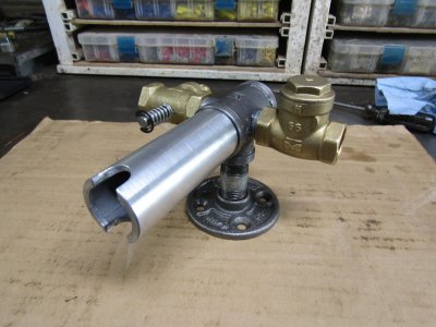
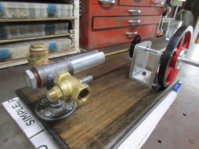
I am pleased to announce there are no interference problems and the compression is better than I expected but it will only decline from here. There is still a lot of empty space to be filled in in the intake and exhaust valves and their connecting piping.
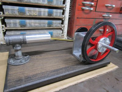
IMG_2356.JPG

The exhaust valve is next on my list.
Thanks for looking
Ray
 
Working on the exhaust valve.
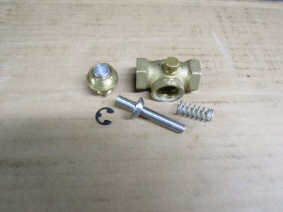
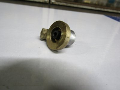
I turned a new steel valve with a 45degree angle and was thinking about re-cutting the valve seat to 45 degrees too but decided against it for now. The seat has a raised narrow rim where the rubber washer would have sealed against. I left it as it was and lapped in the valve and it sealed up nicely.
IMG_2361.JPG

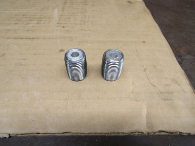
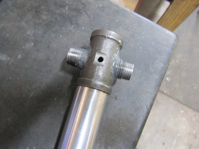
Still trying to use up any empty space to keep the compression ratio up I pressed an aluminum slug into two close nipples and then drilled them out to 5/16" final size. These nipples will be modified so they will screw further into the valve and into the main tee to take up even more space.
IMG_2365.JPG

Thanks for looking.
Ray
 
Thanks Tom

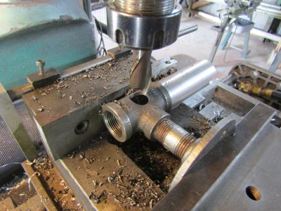
I have been concerned about the wall thickness of the 3/4" tee. This tee is much smaller than the original but I am still using 1/2" plumbing pipes.
I bit the bullet and just drilled the holes to size for 1/2" MIP threads.
IMG_2367.JPG

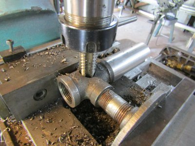
I did the taping in the mill also but not under power.
IMG_2369.JPG

It turned out to be about two or three threads in the tee but the fittings tightened up solidly so I will go with that.
I modified the two close nipples so they would screw further into the tee and into the valves to use up even more space.
Drilled the hole for the spark plug.
Here it is loosely screwed together.
IMG_2372.JPG

I found out quite quickly that the threads in the tee did not make for an air tight seal.
I will tackle that issue tomorrow.

Thanks for looking.
Ray
 
I bought some J-B Weld steel reinforced epoxy rated at 550 degrees. Now all this has to do is seal the threads on the close nipples going into the 3/4" tee. Will have to see it that works.
IMG_2374.JPG

This epoxy takes 4 to 6 hours to setup and 24 hours to cure so I set that aside for tomorrow.

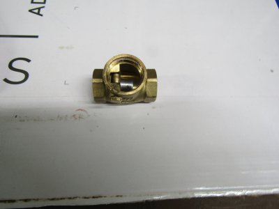
I am going to try to use a steel weight on the intake flapper valve to hopefully get it to seal better.
IMG_2379.JPG

IMG_2380.JPG

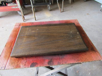
I had only stained the mounting board so since I had some time I gave it quick sand and spayed it with clear coat to help protect it.
IMG_2382.JPG

Thanks for looking.
Ray
 
Maybe a schedule 80 fitting would give you more meat to work with.

Or one of those chunky squared brass ones!

I have thought about using a 5 way fitting and may just do that but for right now the nipples are sealed and I have some compression I just don't know how long it will last when running. Both the intake and exhaust valves have a small leak that I will work on.
IMG_2385.JPG

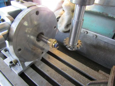
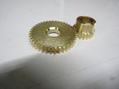
Cutting the timing gears. Mod1 20 and 40 tooth.
IMG_2388.JPG

And the result.
IMG_2391.JPG

Thanks for looking
Ray
 
The build is coming along nicely. Good job!


Sent from my iPhone using Tapatalk
 
Back
Top