- Joined
- Feb 2, 2014
- Messages
- 1,068
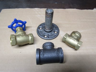
I became interested in the Ford engine years back but never really got the bug to make one until after building the Benz engine. The Benz engine has a sliding plate for the intake valve which is rather odd since he used a regular valve for the exhaust. The Ford engine uses plumbing parts that were available at the time for the intake and exhaust valves. A brass check valve for the intake valve and a shut off valve for the exhaust.
I got these at the local hardware store to get started.
As far as I can find out the original engine had a compression ratio of 2.2 to 1 which is quite low with a 5" stroke. The original piston was 1 1/2" or 1 1/4" in diameter I am not sure which and around 3 feet in overall length. I would like to stay within a 9" x 15" overall footprint or less than 1/2 size of the original.
I will be trying for a compression ratio of 4.5 to 1 but there are several problems with that. I will be using a 3" stroke with a 0.875 diameter piston so I need to make the combustion chamber (the 3/4" tee) and the connecting plumbing much smaller in order to raise the compression ratio.
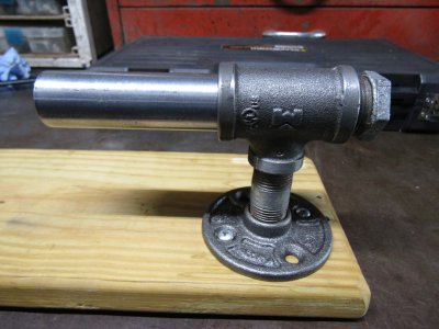
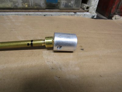
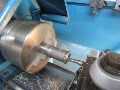
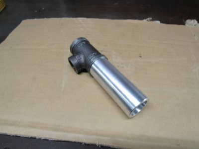
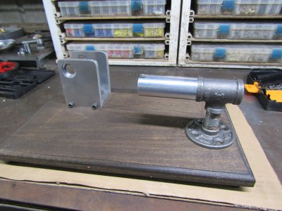
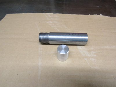
This shows the piston and the seamless cylinder I turned on the lathe. Note the threads are made extra long so the cylinder threads well into the tee and uses up some of the extra room.
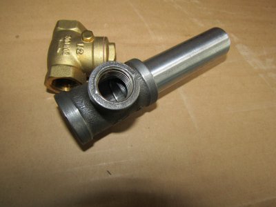
The piston travel will be flush with the cylinder end and can just be seen inside the tee.
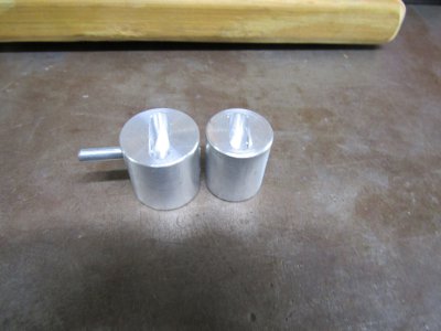
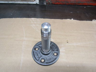
The stand was sealed with an aluminum slug that extends up into the tee to use up some more space.
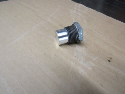
The rear plug also has an aluminum plug that extends into the combustion chamber to use up even more room.
I don't know just how much these changes will make but the combustion chamber is definitely smaller now.
Thanks for looking
Ray
I got these at the local hardware store to get started.

As far as I can find out the original engine had a compression ratio of 2.2 to 1 which is quite low with a 5" stroke. The original piston was 1 1/2" or 1 1/4" in diameter I am not sure which and around 3 feet in overall length. I would like to stay within a 9" x 15" overall footprint or less than 1/2 size of the original.
I will be trying for a compression ratio of 4.5 to 1 but there are several problems with that. I will be using a 3" stroke with a 0.875 diameter piston so I need to make the combustion chamber (the 3/4" tee) and the connecting plumbing much smaller in order to raise the compression ratio.
This shows the piston and the seamless cylinder I turned on the lathe. Note the threads are made extra long so the cylinder threads well into the tee and uses up some of the extra room.

The piston travel will be flush with the cylinder end and can just be seen inside the tee.

The stand was sealed with an aluminum slug that extends up into the tee to use up some more space.

The rear plug also has an aluminum plug that extends into the combustion chamber to use up even more room.

I don't know just how much these changes will make but the combustion chamber is definitely smaller now.
Thanks for looking
Ray


