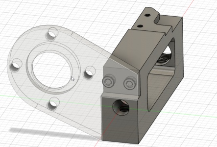
Help with making this two piece part

There is a lot going on with this part.

It would be helpful to know the intended use or at least tolerances. Is this part intended to be used in a wet environment, how much strength is required for the fasteners, etc. It appears that the 1/4-20 hole is partially in each of the two anticipated components. I would be inclined to use an aluminum braze, e.g. Miracle rod, for joining with two dowel pins for alignment. My understanding is the rod is a zinc alloy though, which might not be acceptable in a wet environment. Brazing will also destroy the temper in the aluminum so if strength is an issue, brazing may be a non starter.

Aside from that, a redesign of the part to enable machining from a single block may be the best answer for strength.
It will have a stepper motor hanging on the arm. It does not need strength. Rigidity of the 3/16 thick arm should be plenty.

The current design is one piece. I have only started to think about separating them into two pieces as i dont think it required one piece part for strength. Making each piece separate i think will be easier, but again that is why i am asking those that have much more experience then i do.

Thanks!
Chad
 
Industry would not make a single piece part like that simply because there would be too much wasted material.
Us hobbyists though are not bound by such limits; personally I would make it in two pieces anyhow if only for the simple reason
that it gives you two chances to mess up instead of one. If you mess up one half you won't scrap the whole thing
I like your thinking as i will mess it up many times as i am learning and practicing the operations involved. :)
 
How many of these do you need? Would 3D printing be strong enough? We use it for many jigs and fixtures here at work, metal inserts for threaded features.

John
 
How many of these do you need? Would 3D printing be strong enough? We use it for many jigs and fixtures here at work, metal inserts for threaded features.

John
I am already 3D printing it to test fitment.

I want to move into machining metal now. :)
 
I am already 3D printing it to test fitment.

I want to move into machining metal now. :)
Cool, the 728 is a good candidate for CNC conversion I believe. I see a 4th axis in your future ;)
 
Depending on your design, it may be that a 3D print is good enough. I started out with the idea that I was going to install my DRO on my lathe with all metal parts. I prototyped the parts on a 3D printer last year. Honestly, can't see a reason to swap them out at this point since they are holding up great. If one should die, I'll print up some new brackets. At least I have some confidence that the next print will be awfully close to the previous one!

I thought the parts might sag, but haven't seen any evidence of it. Still can hold settings on the lathe to within a micron if I try. Micron level movement is tricky, as everything isn't quite stable as you think. I rarely need micron accuracy, but it is good to know one can get there.
 

Tapping on a boundary layer seems like a loosing proposition to me. There is a whole lot of wedging force there trying to force the two pieces apart.
Could you redesign this so that the brown piece comes all the way back, and then machine a recessed ledge along the top and left side. The motor flange would then have a rectangle cut-out for the extended portion of the base. You'd then add three or four screws for attachment.
Yeah, i understand what you are saying. I did think of that. I will draw that up and post a new picture. What you suggest means drilling and tapping that 1/4 20 hole into solid metal. not two piece's held together by m3 bolts.
 
Back
Top