Help with Baldor grinder

I'd look at switching the motor on the base so that it is angled in the opposite direction so it tilt toward the front instead of the back. Then I would make a 15° base plate for it. Once the new base plate is under it the wheels should "stick out" towards the front giving you some extra clearance. Then just treat everything else as normal.

Hope that made sense,

-Ron
 
I'm with chips&more and think the end bells on the motor have been rotated. I'd just loosen the bolts and see if they will rotate back level.
 
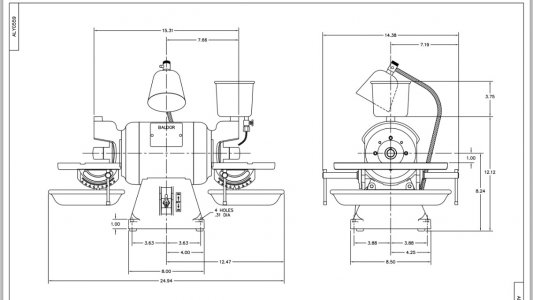
Hmm. Not a whole lot of help but this is the drwg off baldor site. Definitely shows table being level.
ImageUploadedByTapatalk1411425779.503701.jpg

ImageUploadedByTapatalk1411425779.503701.jpg
 
Hmm. Not a whole lot of help but this is the drwg off baldor site. Definitely shows table being level.

I would say that is a lot of help, it shows the guard mount holes square with the base, not canted off 15 degrees. That leads me to believe that the end bells are incorrectly installed.
 
I searched thru all their technical publications and all I could find was generic operation manual etc. nothing showing the exploded motor frame/end housings. I tend to agree might be worth while to loosen the end housings and maybe those are tie rods going thru and the frame could rotate relative to the end housings. I recently had to flip flop the end housings on the new motor I bought for my lathe. The frame is cast iron and had the 4 holes tapped so no tie rods. Pretty easy job. The Op's Baldor motor looks like rolled steel so i doubt there are tapped holes with fixed rotational positions.
 
I can't wait to to see the resolution to this. I think I saw a Baldor grinder jumping the fence in between a couple of sheep. :))
 
First off, thanks to all of you for your responses.

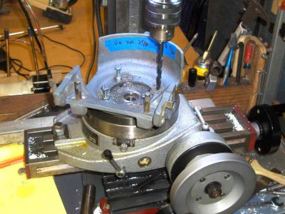
I finally decided that the "most interesting" resolution would be to simply drill a new set of holes in the guards, offset by 15 degrees from the existing ones (and CW at one end, CCW at the other). I know many of you are more confident than I am about loosening the end bells of the motor, but it's just not something I'm comfortable with right now. And besides, the way I did it gave me an excuse to get some use out of my rotary table.

Here's the setup, after finding the rotary's center on the mill, centering the guard on it (using a coaxial indicator for both), and drilling the holes at the requisite 15* offset:

kHPIM3276.jpg

and here's the grinder with the guards re-attached and a new pin for the water supply where the bent one was:

kHPIM3278.jpg

PS -
I'm just thinking that the original water cups were adjustable and they rotate to be level when they are filled. A wing nut and a friction washer would be all it took to hold them once they were adjusted. Just a thought because It doesn't seem like it would work any other way without doing some serious mods to the housings and motor end plates. and like you said it is too nice of a motor to go junking it up too much

Would that it were so simple!! You'll notice two pins between the "ears" at the bottom of the guard. They're what support the water catch tray, and you can see that they're at the same angle (now corrected) as the rest of the guard/table assembly. No independent adjustability, as far as I can tell. Good thought, though ...

kHPIM3276.jpg kHPIM3278.jpg
 
First off, thanks to all of you for your responses.

I finally decided that the "most interesting" resolution would be to simply drill a new set of holes in the guards, offset by 15 degrees from the existing ones (and CW at one end, CCW at the other). I know many of you are more confident than I am about loosening the end bells of the motor, but it's just not something I'm comfortable with right now. And besides, the way I did it gave me an excuse to get some use out of my rotary table.

Here's the setup, after finding the rotary's center on the mill, centering the guard on it (using a coaxial indicator for both), and drilling the holes at the requisite 15* offset:

View attachment 84329

and here's the grinder with the guards re-attached and a new pin for the water supply where the bent one was:

View attachment 84330

PS -


Would that it were so simple!! You'll notice two pins between the "ears" at the bottom of the guard. They're what support the water catch tray, and you can see that they're at the same angle (now corrected) as the rest of the guard/table assembly. No independent adjustability, as far as I can tell. Good thought, though ...


I like your solution, it the solved problem & provided a sense of pride in a "job well done". I don't care if everyone was to say, "well all you had to do is---------------". Thumbs up, good job !

fixit
 
The saga continues ...

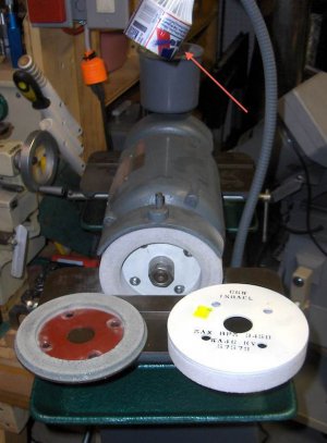
One of my recent quests has been to buy some new grinding wheels. The first photo below shows the sad condition of the 120 grit wheel that came with the grinder.

There seem to be two very popular styles of wheels - unobtainable and overpriced. Very few suppliers carry this style any more, and for many of those who do, their prices can run to well over $150 or more per wheel! As I'd paid only $225 for the grinder itself, this was a bit much for me. [Yes, I know the adage - you'll generally pay as much for tooling as for the original machine tool ... but I'm on kind of a tight budget nowadays]

Then I got lucky. An Israeli company, Camel Grinding Wheels (CGW) sells this style of wheels through Travers Tools http://www.travers.com/ Travers retails through Amazon and eBay. They want about $51/wheel. I ordered three through eBay, and Travers was nice enough to combine shipping and save me about half.

Then I was talking with a friend of mine (and member to this forum), Rick Sparber. He owns a Harbor Freight clone of the Baldor. Turns out he'd ordered two wheels for it a while ago, but the hole pattern did not match. The supplier refunded his $ and told him to just keep the wheels. Rick was nice enough to charge me his cost - zero!

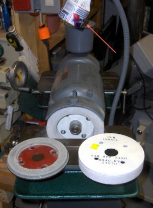
It turns out that the CGW wheels he'd purchased fit perfectly on the Baldor - so it's the HF grinder that has an odd bolt pattern! The first photo shows one of the wheels mounted on the grinder, plus the original used up wheel and my spare aluminum oxide 46 grit wheel. The arrow in the photo points to the "field expedient" lamp shade I added to an LED bulb in the gooseneck socket. The original lamp shade was badly broken.
kHPIM3284.jpg

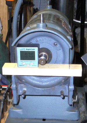
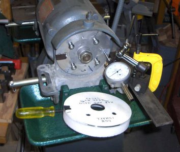
The second photo illustrates how I fixed a runout problem on the wheel mount plates. Both of them had about .006" surface runout. It turns out that Scotch "Magic" Tape is .002" thick. So I set the indicator's zero at the high spot, rotated the wheel until it was .002" low, added a piece of tape, went around to where it was .004" low and gave it two layers, etc.
kHPIM3286.jpg

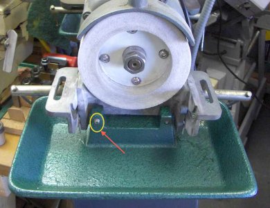
Finally, I wanted to replace the missing water catch trays. Baldor has them for about $80 each. But Grizzly sells a similar grinder, the H7762. And their trays, PH7762022, are under $15 each. I called their help line to check on the hole spacing and it sounded like they would fit. So I ordered a pair. They arrived today - fit PERFECTLY! Both the hole diameters and hole spacing are right on.

Just for paranoia's sake, I drilled and tapped into the end of one pin and added a #8 screw. Now I know that the trays won't walk off if there's any vibration.
kHPIM3287.jpg

About all I have left to do now is to fabricate a tool support, per Rick Sparber - http://rick.sparber.org/ngc.pdf
kHPIM3284.jpg kHPIM3284.jpg kHPIM3286.jpg kHPIM3287.jpg
 
Back
Top