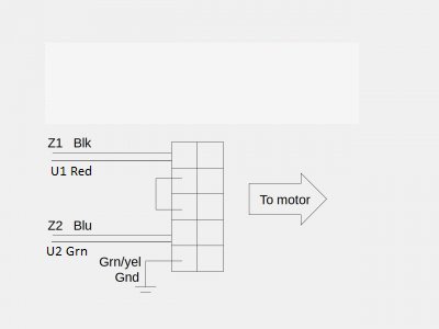
Grizzly G0554 Motor Reverse Wires

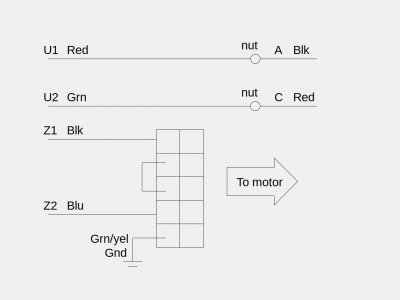
Yes, and the red and green should go to A and C and wirenutted. May need to swap those to get the correct F/R rotation
I downloaded the Lafert catalog- that box SE is a current relay, apparently for starting. Makes more sense now.
Lafertwiring.jpeg
Check and make sure that Red and Green ARE actually U1 and U2- The schematic doesn't indicate
 
Last edited:
Yes, and the red and green should go to A and C and wirenutted. May need to swap those to get the correct F/R rotation
I downloaded the Lafert catalog- that box SE is a current relay, apparently for starting. Makes more sense now.
View attachment 465624
Check and make sure that Red and Green ARE actually U1 and U2- The schematic doesn't indicate


Thank you for that break down. I just want to double check to make sure I am understanding correctly. By doing this you are essentially tying Z1 and U1 together and Z2 and U2 together?

I have verified that the red is U1 and the green is U2. Currently U1 goes to "C" and U2 goes to "A"
 
Essentially yes, the control box ties them together when switching the power legs; the reversing function is obtained by swapping the polarity of the U pair with respect to the Z pair
Is that what you were asking?
The previous owner apparently couldn't make the logical leap to bring out the A and C wires separately, so they just wired it for one direction and left the Z pair hanging
The lack of extra positions on the terminal strip probably added to the confusion
 
Last edited:
Essentially yes, the control box ties them together when switching the power legs; the reversing function is obtained by swapping the polarity of the U pair with respect to the Z pair
Is that what you were asking?
The previous owner apparently couldn't make the logical leap to bring out the A and C wires separately, so they just wired it for one direction and left the Z pair hanging
The lack of extra positions on the terminal strip probably added to the confusion
I think that's what I was asking. Electrical work has never been a strong suit of mine. I just really want to make sure I don't fry something. If I get a chance this weekend I want to draw up a diagram how you did and label it differently to make sure I'm on the same page.
 
I enjoy helping others out with their electrical goblins
Let us know when you get it going- looks like a nice lathe
 
Last edited:
Ok, so I think if I wire it how your diagram shows it essentially does the same thing as this.

Grizzly.jpg
 
Well, yes and no. Only for one direction.
So instead of swapping A and C at the motor end to reverse, it happens at the contactor box side by swapping the start pair to reverse
 
Last edited:
Ok, I am understanding what are trying to do. I hooked it up exactly like you diagram and it runs in both directions with the switch just how it ought to!

Thank you so much for your help, I definitely wouldn't have figured that out!
 
Well, yes and no. Only for one direction.
So instead of swapping A and C at the motor end to reverse, it happens at the contactor box side by swapping the start pair to reverse


Follow up question:
Wiring "A" and "C" directly to U1 and U2 like this does turn the motor forward but it appears that it might also bypass the capacitor. Is that okay?
 
The A and C legs are the main run winding- no capacitors are used with that winding.
The remaining wiring on the terminal block has the complete start leg with caps, start relay and start winding.
The start winding actually does double duty with this motor; it provides some additional run torque also.
 
Back
Top