Grizzly G0554 Motor Reverse Wires

BLev144

Registered
Registered
Joined
Nov 6, 2023
Messages
15
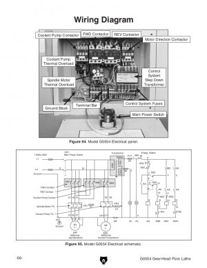
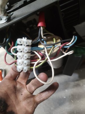
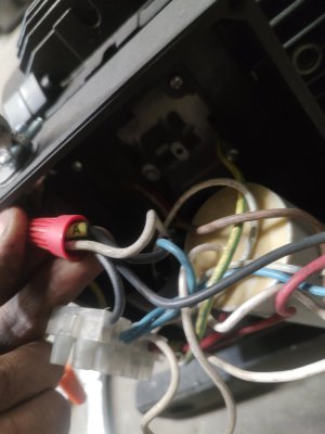
I just acquired a used Grizzly G0554 14x40 lathe. It seems to be a nice machine but it won't go into reverse. When you move the lever to reverse, it runs forward. After chasing some wiring, fiddling with switches and looking at diagrams I pulled the motor and found that these two wires coming from the reverse contacter (Z1 and Z2) do not go anywhere. You can see them on the wiring diagrams going into the motor but there's nothing anywhere that says where they need to attach. I reached out to Grizzly customer support and they were of little help. Does anyone know where these wires attach?

Blue and black wires running from the reverse contacter to the motor.
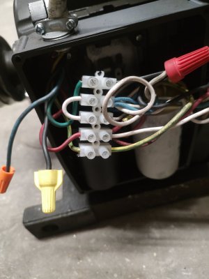


IMG_20231106_070433223.jpg
 
Yeah, gotta have those. Let me look at it for a bit- I shall return
OK you should have 3 wires coming from the control box: U1, U2, and Z1
Looks like a gorilla got into your wiring- or a nesting creature of some type
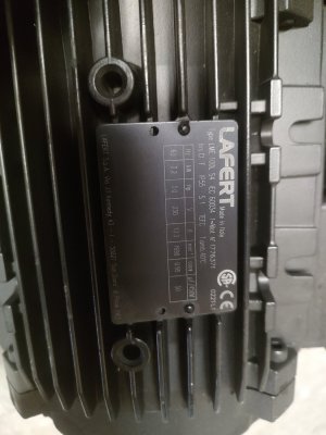
Post a picture of the dataplate on the motor if you canGriz0554schem.jpg
 

Attachments

  • Griz0554schem.pdf
    509.8 KB · Views: 4
Last edited:
Yeah, gotta have those. Let me look at it for a bit- I shall return
I'm kind of going off the assumption that this was a line machine making the same part all the time and they likely eliminated the reverse just so the operator didn't accidentally throw it from forward to reverse at a high RPM. It seems like a pretty low hour machine, I can't really come up with another reason why they would disconnect that.
 
Capacitor start motors can't be reversed without stopping first, so I doubt it was for that reason. Probably just ignorance.
Have to see the dataplate of the motor to begin untangling it
 
Capacitor start motors can't be reversed without stopping first, so I doubt it was for that reason. Probably just ignorance.
Have to see the dataplate of the motor to begin untangling it

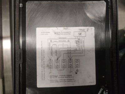
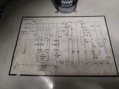
Here's the data tag, wiring diagram on the motor and the one for the machine.

IMG_20231107_120853724.jpgIMG_20231107_120914885.jpgIMG_20231107_120922085.jpg
 
OK, give me a little time to study it- some differences from the manual. Different machine version maybe.
Boy, it's got me scratching my head too and this is not exactly my first rodeo LOL
The picture you posted in #1 : can you straighten the wires out a little so I can see more clearly- mainly that white one that's in the way
This seems like it's a replacement motor-

I think I got it: If you can identify those two black and red that say A and C those should be brought out and go to Z1 and Z2
There aren't enough positions on the terminal block, you'd just have to join them with wirenuts or twist and tape
Then if it runs but backwards just swap those two
It's a cap start and cap run motor but an unfamiliar arrangement to me and the diagram is confusing- no wonder the PO couldn't get it
 
Last edited:
I believe the C wire has a label, but I don't see the A amongst the two black wires-
Might need to do a continuity test with a meter to locate it for certain

Last item: If the above gets the machine working correctly, then one final step should be done:
The two pairs of wires should be swapped:
A and C should be connected to the U1 and U2 since they are the main winding and should go thru FR1 overload relay
Z1 and Z2 should be connected to the currently used terminal strip power pins as they are the start pair
 
Last edited:
Sorry I am just catching up. I didn't see a couple of your edits. Here's the picture with that white wire straightened out a little bit. It runs to the capacitor. The red wire is labeled "c"and the black wire is labeled "A".
It does appear that this is a replacement motor. The tag on the motor says three horsepower and the wiring diagram on the machine says two horsepower. Also it is an Italian motor in a Chinese machine, so...IMG_20231107_173601795.jpgIMG_20231107_173852768.jpg
 
OK thanks, got it. I can see A and C the two you need to break out
That white wire could probably be moved over one space- I don't see why they stuffed 4 wires into one hole when there's only
one wire in the adjacent hole from the jumper- weird.
 
Last edited:
So I basically just need to connect the blue and black wires where the red and green wires go in?
 
Back
Top