Gene Weber's PM-728VT CNC Conversion

I’m about finished with my conversion, have spindle control,last thing is to install my encoder for RPM’s and the air mist system. Mainly do threadmill but want the option for rigid as well.
Have two coats of paint to get on it and then will use self leveling epoxy on the inside of bottom. At the end of the day I’ll probably use air for chip cleaning with minimal mist.
Acorn controls and Teknic SDSK, absolutely loving it.
Homing is a must, 3 switch’s will cover homing and limit.
View attachment 437405View attachment 437406

Love your setup, particualrly the enclosure. I also happen to think that for this size mill, Acorn + Clearpath is the sweet spot.

I removed the handles, DRO and locked the quill. Use the Z-axis control instead.
 
Last edited:
@ChristianSilver that is an awesome setup. Based on the advice I've been getting I will make a plexiglass enclosure once I get my CNC running.

Between work and life, it feels like mine is progressing at a glacial pace. I realized this is sort of like seeing a car, and then deciding to build a great one, without every having driven one, LoL. Someone on the LinuxCNC forum suggested a better way to have gone about this was to mount components on plywood, get one feature working and debugged, and then move to the next. Then design and build the controller box after getting the bulk of the CNC functions working. In retrospect I would also recommend that process. But at this point I don't think there's anything to gain by my tearing stuff out of my controller box.

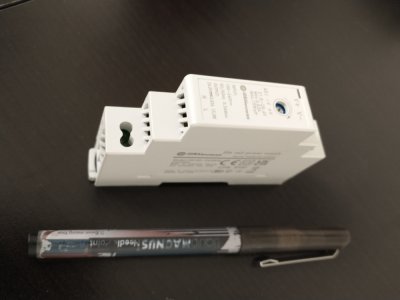
I purchased a PWM Digital to Analog Converter card, and a relay card so I can control the spindle speed and direction. I created a DIN card mount for them as shown in the attached photo. Rather than screw them to the holder, I built cones on the mount for them to sit on. At some point I'll dab some silicone on the projecting points to keep the cards on. My controller did not have the voltage needed for the PWM card, so I added a 24v supply. I bought the little 600mA DIN mount one shown in the attached photo from DigiKey for only $14. Some of this DIN stuff is amazing.
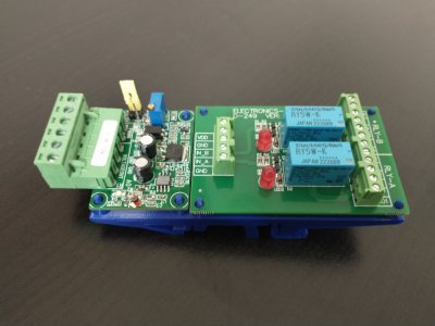
PWM_relay.jpg24v_supply.jpg
I was going to wait till completion to post any wiring diagrams, but the power diagram is hopefully near final, and if I share where I'm at on the signals schematic, people may offer some constructive comments. Everyone has been extremely helpful.

I decided to go the thread milling route if and when I need to do that operation, so no encoder. But I realized it would be very easy to tap into the spindle rpm sensor going into the RPM320M display on the PM-728. I'm using an optoisolator to keep the signal/pwr/gnd separate. I'm not sure exactly what I'll use this for, but it's so easy to do I thought why not. I do realize this does not have the resolution of an quadrature encoder.

This morning I actually logged in to re-read how @koenbro did the limit and home sensors on his setup. I've been reading about limit and home switches the past few evenings. It seems like some people set home at the center of travel for all 3 axes, and others set it full left travel X, full out travel Y, and full up travel Z. If I'm understanding correctly the second method means all X and Y travel are positive from home and all Z travel is negative from home. Is either more typical or advantageous for some reason? Also, any pointers to good write-ups or videos on actually implementing the limit and home switches are appreciated. @ChristianSilver you said you covered limits and home with 3 switches. Can you provide more details?

How many control signals are needed for flood or mist coolant?
How many control signals are needed for a touch probe?

At this point I would just like to make sure I run signal wires for items I add after I get this running. To that end, LinuxCNC and an FPGA card may be more work than other solutions, but they are very programmable/flexible.

Thanks,

Gene
 

Attachments

  • Mill_Cntl_Pwr_V2.pdf
    49.1 KB · Views: 55
  • Mill_Cntl_Signals_V1.pdf
    114.7 KB · Views: 65
[...] This morning I actually logged in to re-read how @koenbro did the limit and home sensors on his setup. I've been reading about limit and home switches the past few evenings. It seems like some people set home at the center of travel for all 3 axes, and others set it full left travel X, full out travel Y, and full up travel Z. If I'm understanding correctly the second method means all X and Y travel are positive from home and all Z travel is negative from home. Is either more typical or advantageous for some reason? Also, any pointers to good write-ups or videos on actually implementing the limit and home switches are appreciated. @ChristianSilver you said you covered limits and home with 3 switches. Can you provide more details?

Following along with great interest and am very impressed by the methodical design and write-up.

For limit switches, do note that there are normally closed and normally open variants. Both will work but if you have a failure in the system (wire disconnect, bad switch etc) the normally closed will add extra protection. I have both, but have chosen NC for my build, although they are a bit more expensive.

I put one on each axis. As you face the mill, to the left end of x (X minus), on the column bottom behind the table for Y minus and at the very top of the column for Z plus. When turned on, the machine will travel (first in z, then y, and finally in x) to hit the switches and that is home. The opposite neds are set in software. You could add a second set of switches ( for X plus, Y plus, and Z minus) but:
1. I did not have enough inputs on the Acorn board
2. complicates mounting and failure points
3. soft limits work safely

So that is one way to do it.

If I were to do it today, I would redesign the mounts such that the switch are not approached head on in X and Y, rather from the side. Hope this makes sense.
 
I used these proximity switches, SN04-P2 PNP NC. 3 each on X and Y and 2 on Z. Z only has home and upper limit. Lower limit doesn't add much value since the tool lengths change a lot. I often have workpieces that are nearly as big as the table, so having limits at both ends of X and Y is a little safer. There were enough tapped holes already, so I didn't need to do any drilling and tapping to mount the switches.
I also used a Mesa 7i76e controller, but those are hard to find now.
 
Back
Top