- Joined
- Dec 19, 2018
- Messages
- 130
So been very busy the past 4 weeks with my 11x29 lathe. Lots of cool upgrades going on ! First is the Little Machine Shop magnetic DRO kit. After much research I opted to buy the LMS "universal" kit so I could custom configure the whole system. You get a 40" long scale and you cut it to length(s) as required. Glad I did this as opposed to trying to fit "pre cut" scales to my lathe.

 littlemachineshop.com
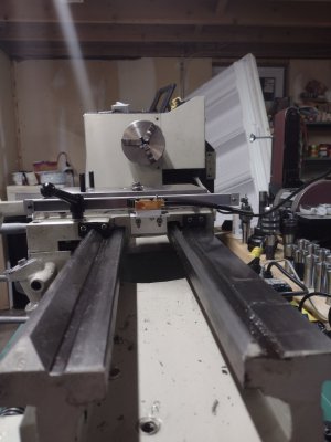
Took a LOT of trial and error mock-ups and fitment considerations but in the end I got everything to fit very nicely on my 9972Z's cross slide. The biggest problem is the "X" axis cross slide gib adj screws are on the same side as you need to mount the scale, and I needed to maintain access to the screws. I ended up completely removing the saddle and drilled and tapped M4 holes in my benchtop mill as it just seemed easier and more precise with locations.
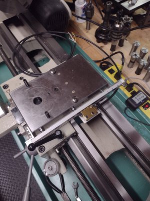
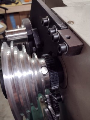
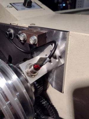
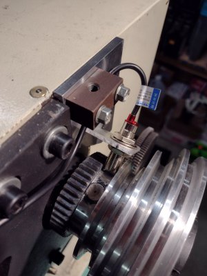
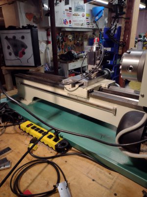
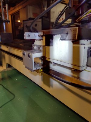
The "Z" axis was much easier mounting the scale but mounting the sensor was more of a PIA as far as complex brackets. The most important suggestion I can make for guys wanting to do a DRO mod is give yourself plenty of adjustment options by machining slots in your brackets ! Here's some pics of the Z axis
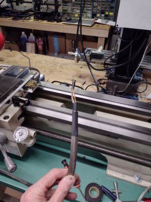
I added stainless woven braid sleeve over the existing sensor cables to help minimize any risk of wear. Used some shrink tube to help cinch the ends.
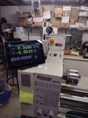
The bluetooth DRO is nice as you can use any tablet.
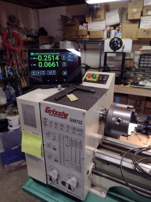
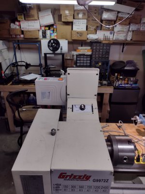
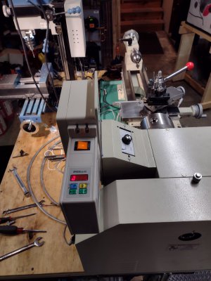
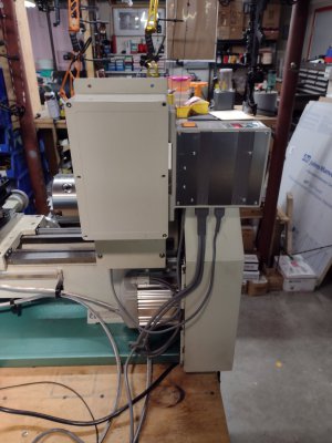
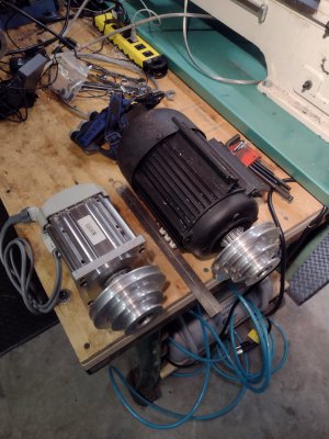
Next up is the Brushless VFD conversion. Finally got tired of belt swaps. There really isnt a bolt in kit for the 11x29 so I had to get real creative. This has been a LOT of work, (still not finished yet) but got all the mechanics finished. Getting all the belt center to center dimensions just right was a PIA but again after a weeks worth of trial and error mock-ups I got all the pulleys aligned and I can still swap belt pulley configurations if needed. The OEM Grizzly motor is 1hp and the new brushless motor is 1500W (2 hp) so this should be a huge improvement in speeds and torque. Here's the universal kit I purchased :

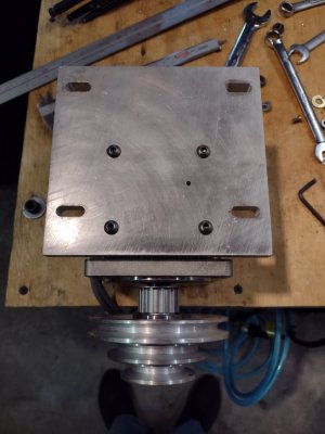
Had to fab a motor adaptor plate out of 1/2" aluminum plate
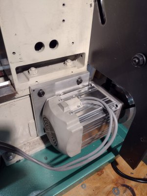
I bought a second motor pulley from Grizzly and modified the pulley to fit the brushless shaft. I had to machine a adapter sleeve, fab a special "stepped woodruff key" , and I had to increase the pulley's counterbore depth so I could attach the shaft nut.
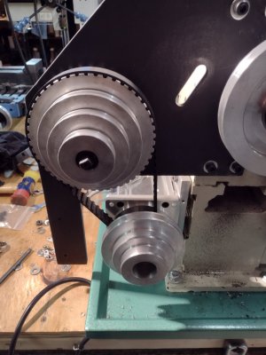
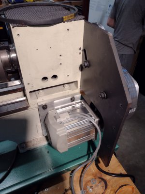
After a week's worth of screwing around with belts alignment's I got it right and the system works excellent.
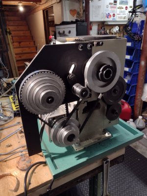
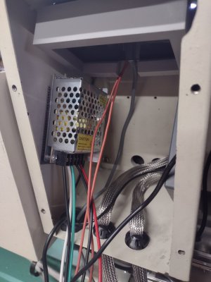
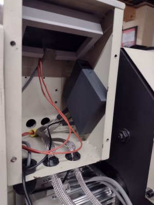
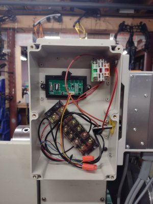
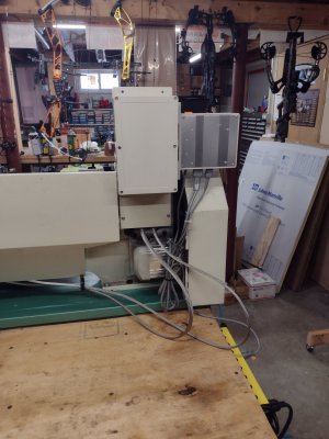
So the last phase of the build is to neatly contain all the electrical switches and speed controller in one box. Not sure how i'm going to do this but I will update as I make progress.

Digital Position Readout, 3-Axis Bluetooth Universal 5515
DRO Packages 5515 Fits milling machines with less than 32" total X-, Y-, and Z-axis travel; Displays on any Android tablet with Bluetooth capability; ...
Took a LOT of trial and error mock-ups and fitment considerations but in the end I got everything to fit very nicely on my 9972Z's cross slide. The biggest problem is the "X" axis cross slide gib adj screws are on the same side as you need to mount the scale, and I needed to maintain access to the screws. I ended up completely removing the saddle and drilled and tapped M4 holes in my benchtop mill as it just seemed easier and more precise with locations.


The "Z" axis was much easier mounting the scale but mounting the sensor was more of a PIA as far as complex brackets. The most important suggestion I can make for guys wanting to do a DRO mod is give yourself plenty of adjustment options by machining slots in your brackets ! Here's some pics of the Z axis


I added stainless woven braid sleeve over the existing sensor cables to help minimize any risk of wear. Used some shrink tube to help cinch the ends.

The bluetooth DRO is nice as you can use any tablet.

Next up is the Brushless VFD conversion. Finally got tired of belt swaps. There really isnt a bolt in kit for the 11x29 so I had to get real creative. This has been a LOT of work, (still not finished yet) but got all the mechanics finished. Getting all the belt center to center dimensions just right was a PIA but again after a weeks worth of trial and error mock-ups I got all the pulleys aligned and I can still swap belt pulley configurations if needed. The OEM Grizzly motor is 1hp and the new brushless motor is 1500W (2 hp) so this should be a huge improvement in speeds and torque. Here's the universal kit I purchased :

2 hp 110V AC Industrial Servo Motor Controller Driver Universal ShopSmith Sheave | eBay
One A type single V belt Sheave Pulley. 3.05" and fit our servo motor. from inferior induction motors to modern design servo motors. A complete servo motor as seen in images. One 1,500 watt (2 HP) servo motor.
www.ebay.com

Had to fab a motor adaptor plate out of 1/2" aluminum plate


I bought a second motor pulley from Grizzly and modified the pulley to fit the brushless shaft. I had to machine a adapter sleeve, fab a special "stepped woodruff key" , and I had to increase the pulley's counterbore depth so I could attach the shaft nut.


After a week's worth of screwing around with belts alignment's I got it right and the system works excellent.

So the last phase of the build is to neatly contain all the electrical switches and speed controller in one box. Not sure how i'm going to do this but I will update as I make progress.


