- Joined
- Feb 7, 2013
- Messages
- 2,487
Some years ago I was at a DNR auction and got some "stuff" on a pallet. On the pallet was a cardboard box
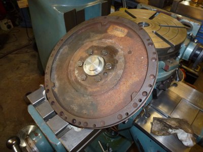
with a truck flywheel in it. So with no use for it, it has been laying around for years. Suddenly it came to me that it
might be a candidate for making a fixture plate. It was rusty but cleaned up really nice and it looks like it has never
been used. I removed the starter gear as that wasn't needed. Next was to fill in a 6 3/8 inch hole in the center of the
flywheel. I used the Monarch to carve out a round piece of 1/2 in thick plate by welding a piece of pipe to the back
of the 6.5 inch square plate. Then it was machined to the proper diameter.
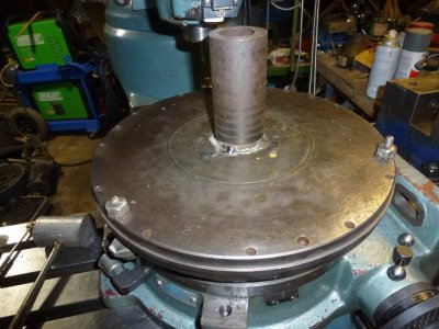
This is the flywheel with the machined part fitted with the new center piece. I welded a pipe on to the plate so that
I could machine a square piece into a round. In this photo I am fitting the machined plate into the flywheel for a nice tight fit.
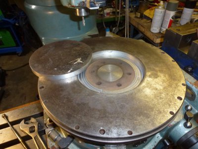
The flywheel had a tapered area on it so milled that material out so the disc would fit inside and flush with the top.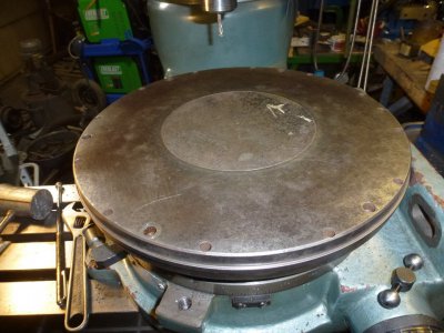
It beginning to look like something I can use now....
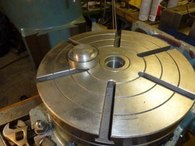
This piece was machined to mate with the table and the small hole in the flywheel center.
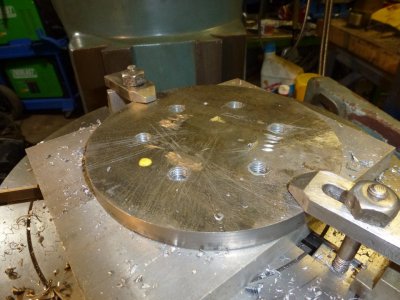
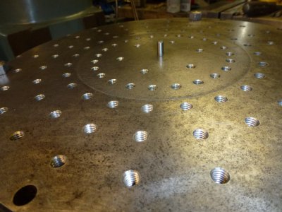
Here I'm tapping the holes I drilled to affix the plate to the flywheel. I didn't want through holes so only drilled in .45 inch
in the 1/2 inch plate. With 6 grade 8 bolts holding it down, it should be just fine.
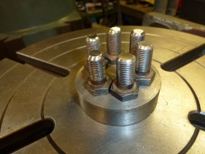
The grade 8 bolts that were actually in the flywheel ended up being a little long so I had to machine off about an eighth of an inch off each one.
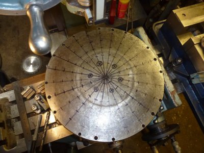
Here I am trying to determine where the threaded holes should go. It made the most sense to me to use the rotary table to position the holes.
I need to think this over before I start drilling. Maybe someone has some thoughts on this configuration. Also, I need to determine what
size the tapped holes will be. Maybe some in 1/2 inch and some in 5/16 towards the center maybe. The circles that are X ed was marked
as a spot not to drill because that is where the bolts are on the underside. One cool thing with the flywheel was that it had 6 equally spaced
holes perfectly spaced 60 degrees apart with smaller holes on each side of them making setup quite easy.
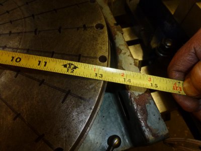
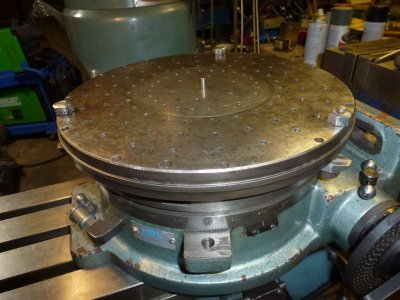
The 12 inch table actually measured 11 3/4 inches and this fixture has a bit of an overhang.
So that's what I have been working for the last couple of days.
with a truck flywheel in it. So with no use for it, it has been laying around for years. Suddenly it came to me that it
might be a candidate for making a fixture plate. It was rusty but cleaned up really nice and it looks like it has never
been used. I removed the starter gear as that wasn't needed. Next was to fill in a 6 3/8 inch hole in the center of the
flywheel. I used the Monarch to carve out a round piece of 1/2 in thick plate by welding a piece of pipe to the back
of the 6.5 inch square plate. Then it was machined to the proper diameter.

This is the flywheel with the machined part fitted with the new center piece. I welded a pipe on to the plate so that
I could machine a square piece into a round. In this photo I am fitting the machined plate into the flywheel for a nice tight fit.

The flywheel had a tapered area on it so milled that material out so the disc would fit inside and flush with the top.

It beginning to look like something I can use now....

This piece was machined to mate with the table and the small hole in the flywheel center.

Here I'm tapping the holes I drilled to affix the plate to the flywheel. I didn't want through holes so only drilled in .45 inch
in the 1/2 inch plate. With 6 grade 8 bolts holding it down, it should be just fine.

The grade 8 bolts that were actually in the flywheel ended up being a little long so I had to machine off about an eighth of an inch off each one.

Here I am trying to determine where the threaded holes should go. It made the most sense to me to use the rotary table to position the holes.
I need to think this over before I start drilling. Maybe someone has some thoughts on this configuration. Also, I need to determine what
size the tapped holes will be. Maybe some in 1/2 inch and some in 5/16 towards the center maybe. The circles that are X ed was marked
as a spot not to drill because that is where the bolts are on the underside. One cool thing with the flywheel was that it had 6 equally spaced
holes perfectly spaced 60 degrees apart with smaller holes on each side of them making setup quite easy.

The 12 inch table actually measured 11 3/4 inches and this fixture has a bit of an overhang.
So that's what I have been working for the last couple of days.


