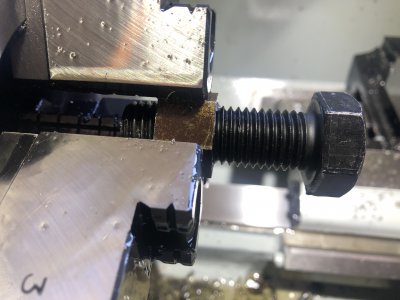
Mikey may have found your problem with the larger thread. If you go to the Dorian website and download their threading tooling catalog, page E20 has a helix angle chart for various pitches and diameters. The M14x2 has an angle around 3 degrees, and the M10x1.25 looks to be about 2.5 degrees. The angle you have your threading tool set to might be enough for the smaller thread, but not enough for the larger one.
-
Welcome back Guest! Did you know you can mentor other members here at H-M? If not, please check out our Relaunch of Hobby Machinist Mentoring Program!
You are using an out of date browser. It may not display this or other websites correctly.
You should upgrade or use an alternative browser.
You should upgrade or use an alternative browser.
First Try at Metric Threading
- Thread starter erikmannie
- Start date
- Joined
- Sep 8, 2019
- Messages
- 4,392
So now I am back to M14-2.0, starting with a female thread. Anything smaller than that (e.g. M12) & my boring bar wouldn’t fit in there. As it is, I had to use a boring bar from my smaller lathe.
Also, I put on the 3 jaw chuck for the hex bar.
This hole (Minor Diameter, from link) is 12.12 mm which is less than 12.210 mm so I can start to cut threads.
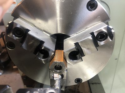
Also, I put on the 3 jaw chuck for the hex bar.
This hole (Minor Diameter, from link) is 12.12 mm which is less than 12.210 mm so I can start to cut threads.
Internal Metric Thread and Fastener Sizes M 9 - M 24
Metric internal thread sizes M 9 - M 24 per. ANSI/ASME B1.13M-1995. These thread sizes and classes represent bolts and screws, as well, as other standard internal threads.
www.engineersedge.com

Last edited:
- Joined
- Feb 13, 2017
- Messages
- 2,138
1) I do reverse the machine after backing out the cross slide for both imperial and metric threading. Because my machine is loose AND I'm prone to lose track of what I'm doing. Cutting metric almost as often as imperial threads, it helps me to have a routine to follow.Question: why don’t people with inch pitch leadscrews leave the half nut engaged throughout the whole operation for Imperial threading as well, as we do with metric threading? It is no trouble at all, and there is no worry about missing the mark on the thread dial. It would coast the same distance if I used the E-stop button.
Second question: I’m curious to see what is going to happen when I try a much smaller safety groove and stop the threading pass with my foot brake. When I disengage my power lever to stop power, it coasts for about 8 mm as the chuck is spinning down.
2) Once the tool is past the cut and power is switched off, braking should have little effect beyond wear and tear on the machine. And that will vary depending on the condition of the machine. Just be sure the switch is off. . .
One thing I noticed was your tool appeared to feed in at 90 degrees. If that is so, the tool is cutting on both sides. I was taught old school, where the feed in is at 30 degrees. Actually 29-1/2. . . So the tool only cuts on the one side.
.
- Joined
- Sep 8, 2019
- Messages
- 4,392
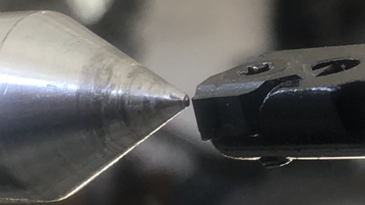
I have centered the tip of the 60° insert.
The most that I will be able to go in there is 1”:
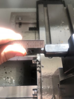
I should have seen that coming and planned for a nut with a length less than 1” and used the open space behind it for a thread relief.
Now I am going to have to go in there with a boring bar and make a thread relief (safety groove).

The most that I will be able to go in there is 1”:

I should have seen that coming and planned for a nut with a length less than 1” and used the open space behind it for a thread relief.
Now I am going to have to go in there with a boring bar and make a thread relief (safety groove).
Last edited:
- Joined
- Sep 8, 2019
- Messages
- 4,392
1) I do reverse the machine after backing out the cross slide for both imperial and metric threading. Because my machine is loose AND I'm prone to lose track of what I'm doing. Cutting metric almost as often as imperial threads, it helps me to have a routine to follow.
2) Once the tool is past the cut and power is switched off, braking should have little effect beyond wear and tear on the machine. And that will vary depending on the condition of the machine. Just be sure the switch is off. . .
One thing I noticed was your tool appeared to feed in at 90 degrees. If that is so, the tool is cutting on both sides. I was taught old school, where the feed in is at 30 degrees. Actually 29-1/2. . . So the tool only cuts on the one side.
.
Thanks!
For external threading, I am only feeding in using my compound hand wheel so I believe I am going in at 30°. I usually set mine to 29 1/2°, also.
- Joined
- Sep 28, 2013
- Messages
- 4,318
another tip Erik - chamfer the beginning and end of the piece you will be threading before you cut the threads. You can use the threading tool to do this or a dedicated chamfering cutter, doesn't really matter. Makes the finished product look and work better.
- Joined
- Sep 8, 2019
- Messages
- 4,392
I failed. The Aloris threading bar that I’m using specifies that the beginning hole must be a 1/2” or larger, and my beginning hole was just a hair over 12 mm.
It went down very badly. It would make a fine cut going in, and then there was not enough room to retract the threading bar, so the 60° tip did a little damage on its way out. Very ugly.
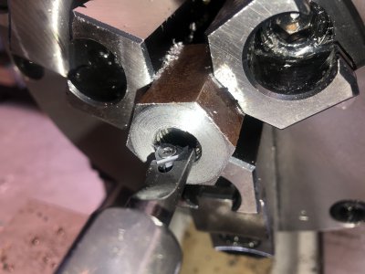
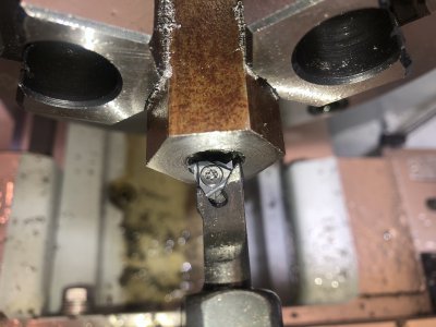
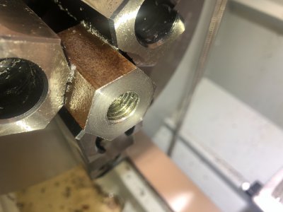
It went down very badly. It would make a fine cut going in, and then there was not enough room to retract the threading bar, so the 60° tip did a little damage on its way out. Very ugly.


Last edited:
- Joined
- Sep 8, 2019
- Messages
- 4,392
I have an M20-2.5 nut & bolt. I am going to try to make a nut.
It looks like I start with a (chamfered!) hole (minor diameter from link) of between 17.244 and 17.744 mm.
An 11/16” drill is 17.46 mm so that should work.
It looks like I start with a (chamfered!) hole (minor diameter from link) of between 17.244 and 17.744 mm.
An 11/16” drill is 17.46 mm so that should work.
Last edited:
- Joined
- Sep 8, 2019
- Messages
- 4,392
That was challenging. I busted an import HSS preground grooving/parting tool because I was feeding in too quickly; I may have also had too much tool stickout.
Then I got sidetracked & struggled to drill a hole in my MT drift so that it would hang on a hook on the wall. The material of the drift (tool steel?) was harder than the material (HSS?) of the import drill.
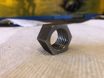
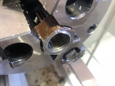
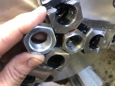
I had not noticed until I did this that the interior of a nut this size does not have a crested V at the minor diameter. I will show my threads and a stock nut in the photos. I was expecting a crested V.
The interior threading went fine. I came out a radial .09275” on the DRO. I was getting almost as many chips on the spring passes that I was on the threading passes. I don’t know why that is, but it was frustrating.
Most of the passes were a radial .005”.


Last edited:
- Joined
- Sep 8, 2019
- Messages
- 4,392


