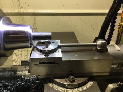
There's a lot for me to digest here but thanks. In terms of loads my primary use for this ball turning jig is for turning a 3/4" ball from 3/4" mild steel rod. I also would have another hole for the cutter to do the same for a 3/8" ball made of mild steel.I agree that, in general, identifying degrees of freedom is important. But you need to do more. Here, you want a single degree of freedom (rotation about the vertical axis). Now you need to identify loads. You have, as I understand it in the example, primarily axial loads. So different 1-DOF rotational joints will handle loads differently. A deep-groove ball bearing will handle some axial load but that's not it's strong point. A thrust bearing will handle axial loads, but not radial loads, and most will not handle radial alignment (i.e., they are not suitable for restraining all but 1-DOF).
A tapered roller bearing is great at a mixed axial and radial load, but they require preload (a force smashing the two halves of the bearing together). Generally, they are used in opposing pairs, so that they preload each other essentially. If, as here, you have unidirectional axial loading, you could use a single one as long as the preload is sufficient. What does that mean? It depends on the applied load. If you have a pure axial load, then really no preload necessary. But as soon as the bearing needs to resist a moment from radial loading away from the plane of the bearing, then you need preload. Better than that would be a second bearing.
What is difficult about what you're asking is that is is too simple. You need much more than what the joint is called. And there are many ways that such a joint could be constructed, depending on constraints. Bushings (plain bearings) are good for low speed, high load, but will have more friction than rolling-element bearings.
It seems like physical size is important to you. So you may think about a solution that can nest the two structures (one for radial/moment loads, one for thrust). How about a cylindrical bushing to keep everything centered? That would restrains 4 degrees of freedom, leaving 2 unconstrained (axial movement and rotation about the primary axis are unconstrained, while movement along and rotation about the transverse axes are constrained). Then add a needle thrust bearing on bottom to handle the axial load (restrains axial movement). That seems like a potentially good approach.
You could do as Dave suggests - a single bearing. But not many bearings are well suited to operate in that configuration with your proposed loading. I've been considering the ball turner but you mention another jig that you are interested in. It's entirely possible that the jig would work really well with a single deep-groove ball bearing. Even the ball turner might if we can estimate the loads a little and check available bearings.
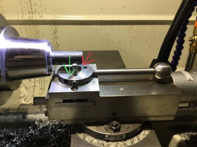
The Sehr version I made does work but it's kinda sloppy. (My fault.) I have to be pushing down on the disk opposite the cutter otherwise the disk has wobble and thus does not cut cleaner and perfectly at the center, (3/8" up the 3/4" rod).
Lastly, searching on DOF came up with a lot of cool related stuff.