Engineering principle behind this type connection

Maplehead

Registered
Registered
Joined
Feb 20, 2017
Messages
437
Hi All
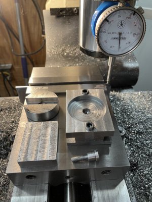
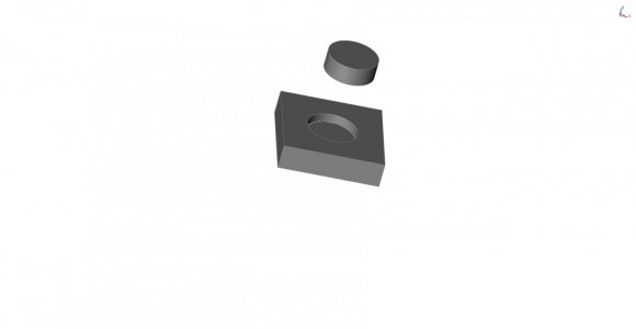
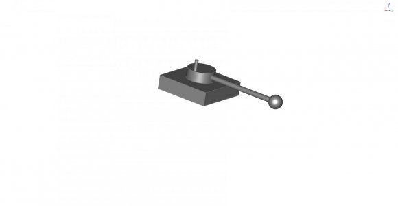
I want to research how to make a certain type of mechanical connection. I don't know the nomenclature but basically it's the concept of a rod or cylinder in a hole/bore that turns on its axis. In the provided pic you can see a previous, disassembled radius turning jig I had made using the above concept. (I use the Jim Sehr design now.) I have two jigs I want to make. One being my Jim Sehr ball turner because my connection at the turning part slightly wobbles so I want to remake it better. In my method a screw underneath the jig pulls together the male round part into the female round part. However, if I want the two pieces snug and tight then I need to tighten the screw, but if I do then the male piece turns with greater difficulty/resistance in the female piece. On another jig I will be making a horizontal connection of this type.
So how do I make these connections fast without increasing the resistance to turning? I'm sure bearings will come into play but I can never wrap my head around how they connect in. As usual, any and all help/advice is greatly appreciated.
 

Attachments

  • 53908CC8-6D72-47DE-9C52-A457F1C06BE7.jpeg
    53908CC8-6D72-47DE-9C52-A457F1C06BE7.jpeg
    100.4 KB · Views: 89
I'm not an expert here, but it would seem that a large tapered roller bearing, like a big farm machine wheel bearing could be useful. An old used one would work even if it had some wear, as long as it was still smooth. The center bolt might want a small thrust bearing against the top of the rotating plate. You could adjust out all unwanted wobble and still rotate smoothly with little effort.
DanK
Thanks for the reply Dan. What I would love is the nomenclature on this type connection so that I can research it and see diagrams on how the connections are made and affixed. I've tried looking up different things but it's that game whereby if you don't specify the exact words then you can never find it.
 
Im confused on what you're trying to accomplish here .
 
I think it’s just a rotary joint (rotational joint, pivot, etc.), and in particular one that can handle a primarily thrust load. Many examples. You’re looking for an axially compact version. I like the idea of a single tapered bearing with a thrust bearing on the preload screw.

You could do it with bushings (plain bearings) but I’d think then you want no taper, just a bore for radial forces and a flange for axial forces. Maybe use a spring on the preload screw so you have a more repeatable and stable preload. e.g. a Belleville washer under the head. Don’t need much preload really since the forces do no try to separate the bearing. You would need very good control of your radial dimensions to eliminate slop.

The tapered roller bearing doesn’t have that problem of tolerances, but does require reasonably good fits for the bearing races. Not as critical, and line fits or slight clearance may be dealt with by retaining compound.
 
Im confused on what you're trying to accomplish here .
Two things: What is the technical name for this type arrangement/connection and two, how best to make it?
So referring to my simple drawing here, the disk will be inserted into the hole. I want the disk to turn easily and smoothly around the axle but I do not want it to move along the axle. Bearings or no bearings? Use a screw as the axle with a lock nut or something else like a shaft through a bushing? If I could just get the technical name for this and look it up and then find some simple, straighforward pics on how they all connect together then I'd be good to go.
 

Attachments

  • A31931D3-A62F-4D0F-A31B-4E7E74338CB8.jpeg
    A31931D3-A62F-4D0F-A31B-4E7E74338CB8.jpeg
    19.5 KB · Views: 53
In general terms you might want to look at the problem in terms of how many degrees of freedom you want to permit. Up to a point, grooved thrust washers can constrain radial and axial motion and permit rotary motion.
 
Why not just press a bearing into the block and machine a shaft with a very light press or slip fit for the top ? Either a lock collar or adjustable threaded ring on the bottom would pull it tight without binding . Even better , a top and lower bearing to support the business end .
 
I agree that, in general, identifying degrees of freedom is important. But you need to do more. Here, you want a single degree of freedom (rotation about the vertical axis). Now you need to identify loads. You have, as I understand it in the example, primarily axial loads. So different 1-DOF rotational joints will handle loads differently. A deep-groove ball bearing will handle some axial load but that's not it's strong point. A thrust bearing will handle axial loads, but not radial loads, and most will not handle radial alignment (i.e., they are not suitable for restraining all but 1-DOF).

A tapered roller bearing is great at a mixed axial and radial load, but they require preload (a force smashing the two halves of the bearing together). Generally, they are used in opposing pairs, so that they preload each other essentially. If, as here, you have unidirectional axial loading, you could use a single one as long as the preload is sufficient. What does that mean? It depends on the applied load. If you have a pure axial load, then really no preload necessary. But as soon as the bearing needs to resist a moment from radial loading away from the plane of the bearing, then you need preload. Better than that would be a second bearing.

What is difficult about what you're asking is that is is too simple. You need much more than what the joint is called. And there are many ways that such a joint could be constructed, depending on constraints. Bushings (plain bearings) are good for low speed, high load, but will have more friction than rolling-element bearings.

It seems like physical size is important to you. So you may think about a solution that can nest the two structures (one for radial/moment loads, one for thrust). How about a cylindrical bushing to keep everything centered? That would restrains 4 degrees of freedom, leaving 2 unconstrained (axial movement and rotation about the primary axis are unconstrained, while movement along and rotation about the transverse axes are constrained). Then add a needle thrust bearing on bottom to handle the axial load (restrains axial movement). That seems like a potentially good approach.

You could do as Dave suggests - a single bearing. But not many bearings are well suited to operate in that configuration with your proposed loading. I've been considering the ball turner but you mention another jig that you are interested in. It's entirely possible that the jig would work really well with a single deep-groove ball bearing. Even the ball turner might if we can estimate the loads a little and check available bearings.
 
Two things: What is the technical name for this type arrangement/connection and two, how best to make it?
So referring to my simple drawing here, the disk will be inserted into the hole. I want the disk to turn easily and smoothly around the axle but I do not want it to move along the axle. Bearings or no bearings? Use a screw as the axle with a lock nut or something else like a shaft through a bushing? If I could just get the technical name for this and look it up and then find some simple, straighforward pics on how they all connect together then I'd be good to go.
End result would be a smoothly funtioning "Jim Sehr" ball turner as seen in the simple pic.
 

Attachments

  • 67900AE0-798F-449E-9A7B-3AB151E40F46.jpeg
    67900AE0-798F-449E-9A7B-3AB151E40F46.jpeg
    20.1 KB · Views: 47
Back
Top