- Joined
- Mar 20, 2013
- Messages
- 153
Thanks Bob.
Jerry
Jerry
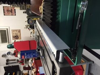
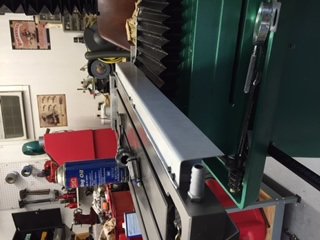
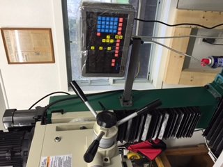 Well I finally got the x and y axis scales mounted. Bob, I looked at mounting the x scale to the front but with the stop switch for the drive, it looked like I would have had to stick it out quite a bit. So, I mounted it on the back. There was an oiler for the gibs in the middle and I made an L mount there to bring the ball oiler up to the top of the scale cover. On the Y, I followed your drawings(loosely since I was using stuff out of my scrap bin for the mounts). It came out OK and I'm happy with the results. Now to do the z. Thanks for all y'all's input.
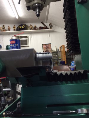
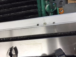
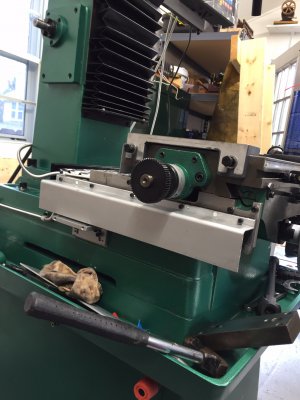
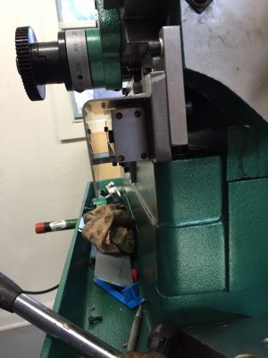
My recollection is that there was some rotational play in the spindle and that I used an additional stop to limit that rotation as it affected the alignment of the pickup to the scale. You would have to modify the hole in the bottom of the head to control that play. You will also have to modify the front plate on the head to accommodate a bracket for mounting the pickup. Maybe the head casting as well.
It's been over four years and I'm a bit fuzzy on it. I can see if I can get some photos of the actual setup.
Bob
Rotational movement to the left is limited by the mounting bracket for the DRO. As I recall, I added a second piece to the right which limited the rotational movement to the right to a few thousandths. It was a fairly small piece, on the order of 1/4" x 1/2" x 1" and mounted directly to the mill head housing. I made a couple of screen shots of the the bottom and front view of the SolidWorks model but I seem to have a problem uploading files right now. I will post them when things are working again.Bob, thank you for your posts and pics. They really helped. I've been traveling and haven't had time to work on my mill but I have the x and y installed and have made the brackets for the z. I am in the process of installing the z brackets and getting them parallel and plumb. The problem I'm working on is the rotational torque and overcoming that. You mention an additional stop and modifying the hole in the bottom of the head to control the play. Would you be so kind to explain that? Thanks,
Jerry
Still trying to upload file with no joy. I will try again later.Bob, thank you for your posts and pics. They really helped. I've been traveling and haven't had time to work on my mill but I have the x and y installed and have made the brackets for the z. I am in the process of installing the z brackets and getting them parallel and plumb. The problem I'm working on is the rotational torque and overcoming that. You mention an additional stop and modifying the hole in the bottom of the head to control the play. Would you be so kind to explain that? Thanks,
Jerry
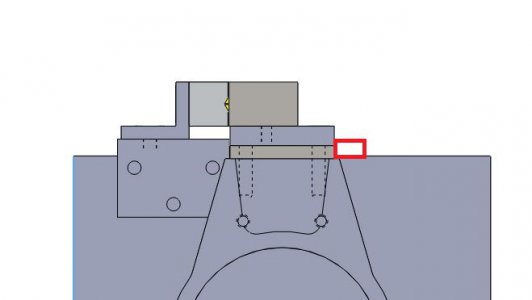
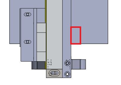
Jerry, It appears that I can now upload files. Here the bottom and front views. The block limit rotation to the right was in the location shown in red. You can also see some of the detail as to how I mounted to the existing bracket for the quill stop.Rotational movement to the left is limited by the mounting bracket for the DRO. As I recall, I added a second piece to the right which limited the rotational movement to the right to a few thousandths. It was a fairly small piece, on the order of 1/4" x 1/2" x 1" and mounted directly to the mill head housing. I made a couple of screen shots of the the bottom and front view of the SolidWorks model but I seem to have a problem uploading files right now. I will post them when things are working again.
It has been several years since I last saw the mill. It happens to be in the possession of a friend and I had asked him the take some photos of the setup. I will re-ping him.
