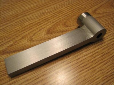
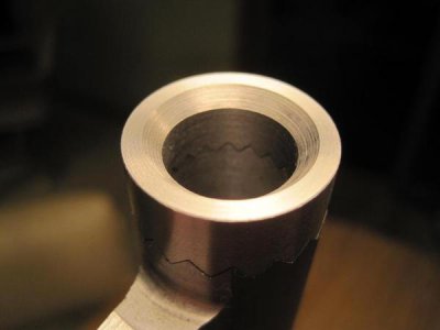
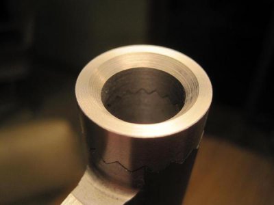
Cutting 90 degree v groove with pointed end mill

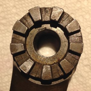
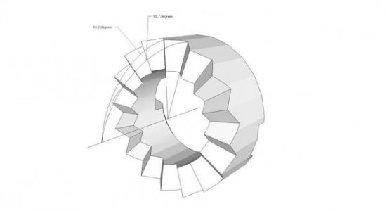
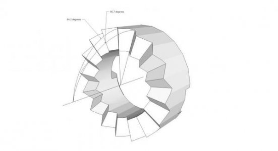
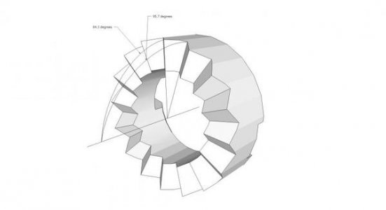
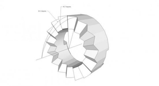
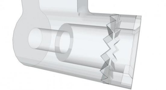
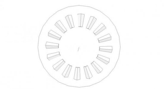
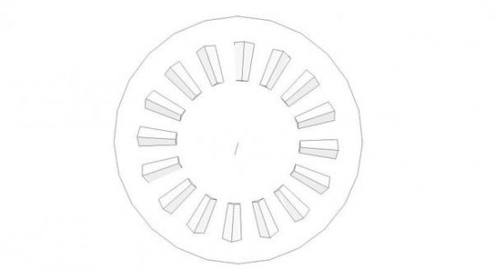
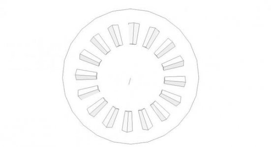
Dave, you're mostly right about indexing to each tooth or vee, I guess. The vee is 90 degrees along it's entire length, though--so no need to cut each face of the vee separately. My screw-up is that I cut all 16 teeth on the wrong side of the blank, so they're *all* angled wrong. . . . So, you're right--you can't increment 8 times and get the correct angle all the way around. You wouldn't want to do that anyway though because the blank is sitting at 5.7 degrees, so depth wouldn't be the same anyway.

Jim


Lookin good Jim, But I think you will find if you machine the V in one pass the two parts will match up and you will have V looking cuts. But they will only mesh together on the outside diameter of the two parts when joined. There will be no other contact of the V’s mating surfaces. You will have air space and more of it as you go towards the center of the part. Each face of the V must point to the center of the part, not just the bottom of the V pointing to the center of the part…Good Luck, Dave.
 
Lookin good Jim, But I think you will find if you machine the V in one pass the two parts will match up and you will have V looking cuts. But they will only mesh together on the outside diameter of the two parts when joined. There will be no other contact of the V’s mating surfaces. You will have air space and more of it as you go towards the center of the part. Each face of the V must point to the center of the part, not just the bottom of the V pointing to the center of the part…Good Luck, Dave.

I know what you're saying, but I think you're wrong! I have consulted machinery's handbook, and I'm applying the information in there to create my setup. I've also modeled these parts in SketchUp, so pretty sure of myself. . . .
That doesn't mean that I'm not wrong, but I feel pretty good about it. :victory:

Jim


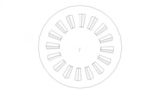
Well then, maybe study the below pic. It does not have V’s, but the theory is the same.

vee.JPG

vee.JPG
 
Yeah, that's the same--but different.

ShaperF2_zps88736499.jpg

See how the edges are angled towards the center? That angle is enough to allow the planes of the ridges to remain at 90 degrees.


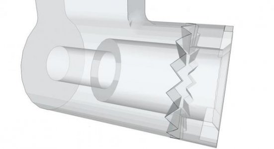
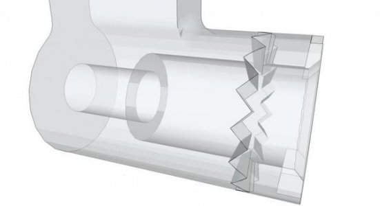
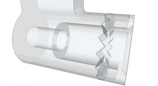
Here's what it looks like when the parts are meshed together.

ShaperF1_zpsd76b95b0.jpg


Jim

ShaperF2_zps88736499.jpg

ShaperF2_zps88736499.jpg

ShaperF2_zps88736499.jpg

ShaperF1_zpsd76b95b0.jpg

ShaperF1_zpsd76b95b0.jpg

ShaperF1_zpsd76b95b0.jpg
 
Here, take a look at this one:

ShaperF3_zps14e10f62.jpg


I took the drawing from my last post and drew a circle that goes through the axis where those lines converge. That looks a little better, eh?

Jim

ShaperF3_zps14e10f62.jpg

ShaperF3_zps14e10f62.jpg

ShaperF3_zps14e10f62.jpg
 
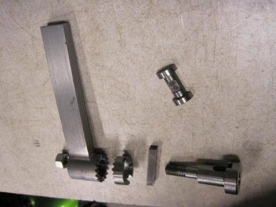
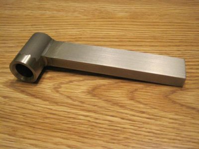
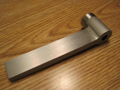
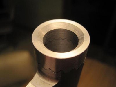
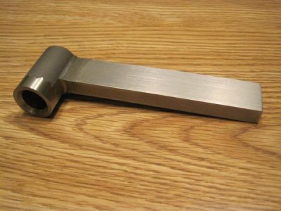
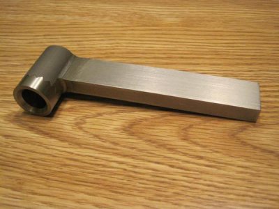
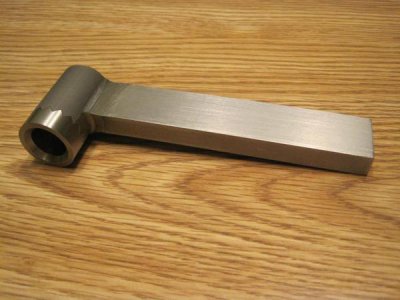
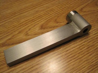
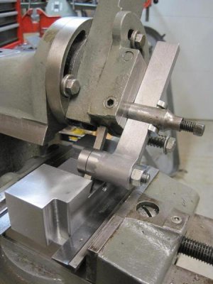
Finished up the main portion of the shaper tool. I'm pretty happy with how it turned out. Here's a couple pics

IMG_4921_zps1a899ca7.jpg


IMG_4920_zps168fbff8.jpg


IMG_4919_zpsb0b3fce6.jpg

Jim

IMG_4921_zps1a899ca7.jpg

IMG_4921_zps1a899ca7.jpg

IMG_4921_zps1a899ca7.jpg

IMG_4920_zps168fbff8.jpg

IMG_4920_zps168fbff8.jpg

IMG_4920_zps168fbff8.jpg

IMG_4919_zpsb0b3fce6.jpg

IMG_4919_zpsb0b3fce6.jpg

IMG_4919_zpsb0b3fce6.jpg
 
I get all the theories about how much contact the part will have, but what matters is it works for you! Good looking part.
 
You could have left your mill set to vertical and instead tilted your dividing head...
 
It's difficult to see in the pics, but the dividing head is already tilted at 5.7 degrees. That's the angle that is necessary to get the teeth to engage along their full length.

Tilting the head seems like the best solution to me as I don't have anything that tilts and is large enough to hold the dividing head.

Jim
 
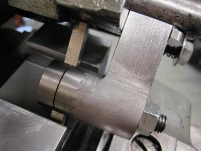
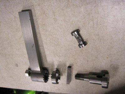
I wanted to post a follow-up on this. Here's a few pictures
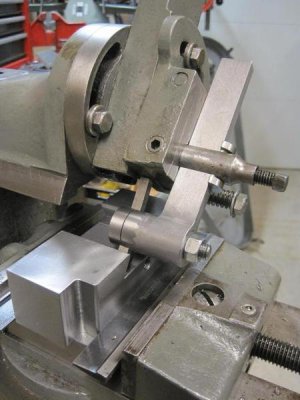
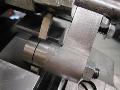
IMG_5002_zpses8dzofh.jpg

IMG_5003_zpskw3u7h5j.jpg

IMG_5068_zpswacgxdut.jpg


I had finished the shaper tool some time back, but had a few problems when I first used it.

First some background--I had been using an Armstrong-type, straight-shank lathe tool with the shaper and had good success on most operations. The only thing was that cutting dovetails was a problem. Due to the geometry involved--the lathe tool puts the cutting edge way out in front of the clapper--so the tool wants to bind, catch, and dig-in. This is a big problem when in that tiny corner where the two surfaces of the dovetail meet. That's why a decided to build the shaper tool in the first place.

The first time I used the new tool I didn't have a dovetail to cut--just decided to take a nice deep cut on a scaly old piece of scrap. . . . That's where shapers excel, right? Anyway, everything started out fine for the first few cuts. Even after an inch or so of feed, it was still OK. . . . Then I noticed that the depth of cut seemed to be increasing. That's funny, that had never happened before. What's up right? I thought maybe the toolbit was slipping out of the tool-holder. It was plenty tight. Maybe the tool was slipping? A few more cuts, and it kept repeating. I couldn't get it to work even as well as the lathe tool had!

I was kind of disgusted with it at that point, so left it for a few days and came back to it. . . . Then I was making another lathe tool-holder w/ dovetails, so got it back out again. It didn't take very long to find the problem. Neither the tool-holder, nor the bit was slipping. The shaper was self-feeding! I didn't have the gibs tight enough for use with this tool. What had always worked with a lathe tool wasn't working here. Once I got the gibs tightened up, it works fine.

Still, I'm wondering now if there's something a little "off" with my design. Maybe the 5 degree angle of the toolbit or the long distance behind the clapper exaggerates this effect?

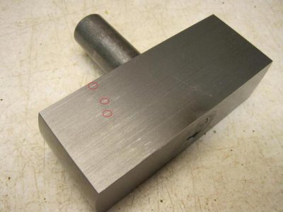
I've also noticed that the geometry cause another problem that I hadn't seen with the lathe tool-holder. Look at this picture.
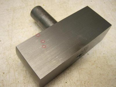
Marks-001_zpscnq49poe.jpg


There are some very light marks that are about 3/16" long in the foreground there--I've got three of them circled in red. This happens when clapper bangs the toolbit down on the work on the return stroke. The effect was much worse before I rounded off the back of the toolbit. Now it's better, but as you can tell, still noticeable.

Any thoughts on corrective actions for that? Maybe I'll end up just using this tool for dovetails. . . .

Jim
IMG_5002_zpses8dzofh.jpg

IMG_5003_zpskw3u7h5j.jpg

IMG_5068_zpswacgxdut.jpg

Marks-001_zpscnq49poe.jpg
 
Back
Top