Compound Delete

To each his own I guess.
I learned to cut threads, short tapers and accurately face things off using the compound.
Now I'm hearing get rid of the compound, make or buy a doohicky to replace it and get a DRO which I've never needed.
Nah, I'll continue doing it the way I was taught.
I would agree. Almost all of my machines spent their previous lives in a commercial or industrial setting. They seemed to have worked well for their previous owners for many years without needing to be modified.
 
I think that Renzetti and Gotteswinter and most other Youtubers tend to do things to their machines and tools for the main purpose of getting views and subscriptions. I bought a large block of steel for making a rigid mount toolpost for my Grizzly G0206 (Edit G0602) lathe because everyone else was doing it but have never felt the need to use it.

If I did go ahead and machine the block, I would continue using the indexing toolpost setup as shown in the attached pics. I can see having a rigid mount on a CNC machine where most any taper or chamfer can be easily programmed but, on a manual engine lathe, I would be lost without the capability of setting regular cutting tools on various angles. It is so convenient to quickly loosen the toolpost and index the QCTP to a desired angle.

My design will index in five degree increments and then easily index back to the home position for normal turning, facing or cutoff. The toolpost stud is held in place and a snug fit in the toolpost for accuracy.

The index quadrant shown attaches to the side of the toolpost so as to not change the height.
 

Attachments

  • TOOLPOST-INDEXING-QCTP-4.jpg
    TOOLPOST-INDEXING-QCTP-4.jpg
    107.2 KB · Views: 23
  • TOOLPOST-INDEXING-QCTP-5.jpg
    TOOLPOST-INDEXING-QCTP-5.jpg
    95.8 KB · Views: 24
Last edited:
Almost all of my machines spent their previous lives in a commercial or industrial setting.
To be fair, the class of lathes you're talking about probably wouldn't have the rigidity problems that removing the compound would help with.

Would it be the kind of lathes that don't have the mass and consequent rigidity that might benefit from this? Mini-lathes and the like.
 
To be fair, the class of lathes you're talking about probably wouldn't have the rigidity problems that removing the compound would help with.

Would it be the kind of lathes that don't have the mass and consequent rigidity that might benefit from this? Mini-lathes and the like.
That's why I did it. The 7x12 mini lathe isn't all that beefy.

Regarding the DRO and handwheel on its leadscrew, they were done for a completely different reason. I bought a relatively cheap ball turner that installs in place of the compound. That prompted the mods because it was pretty difficult to use in the absence of a good way to advance the ball turner into the work. Plus I couldn't lock the carriage (because it was the only way to advance the cutter) so the cutting forces were pushing it away from the work. Both have come in handy for other purposes.
 
About compound movement while turning.... Move the compound back so there is no overhang, lock the compound so it can't travel. I don't use the compound a lot but it is handy for some operations. Not needed for threading since I thread straight in and away from the chuck.
 
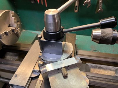
That's why I didn't get rid of my compound :). But now if I had to I could cut threads without the compound. I could use my z-axis DRO and handwheel on my lead screw to approximate the motion of the compound set at 29.5 degrees. One nice result of this approach is that your cross slide directly indicates the depth of the thread you are cutting so you are getting something back for the additional work of advancing two cutting axes.

Some don't bother with setting the compound over, they just plunge cut. This approach also doesn't require a compound.
I'm trying to understand what you're saying here and wondering if you are referring to the z-axis as the carriage travel parallel to the spindle per the normal convention. I assume by "handwheel on my lead screw" that you're referring to the x-axis as in cross-slide?

Not sure how you could change the z-axis position as it is tied to the thread gearing.
 
I'm surprised that so many members are considering modifications to eliminate the compound. I would be interested in knowing what brand machines are needing these modifications. I have a 1960's era Sheldon, and an early 1900's Seneca Falls machines and neither of them have rigidity issues. They are both used hard (within their capacities) and can easily produce parts to well within the spec range, with excellent finishes.
On my Emco V10p the only qctp size available that fit the compound is OXA. Making a solid post meant I could size it for AXA for cheaper and more common sized tools.
 
I'm trying to understand what you're saying here and wondering if you are referring to the z-axis as the carriage travel parallel to the spindle per the normal convention. I assume by "handwheel on my lead screw" that you're referring to the x-axis as in cross-slide?

Not sure how you could change the z-axis position as it is tied to the thread gearing.
Yep, z axis. And no, I'm not referring to the cross slide.

If the half nuts on the carriage are engaged with the LS but the gear chain is disengaged, turning the LS by using the handwheel moves the carriage independently of the spindle. It's 16TPI so a bit coarser than the 20TPI compound feed screw. Not really an issue, given the fact that my DRO indicates movement on the z axis.

Since the LS wasn't designed for this kind of use, there's a lot of clearance between the LS and its mounting brackets. This causes a significant amount of backlash. That's not an issue for cutting threads but makes it harder to make fine adjustments on the z axis. So I did a later modification where I replaced the right-hand bracket with one that incorporates two thrust bearings (one on each side of the bracket) and a nut-based preloading scheme. The mod reduced the backlash quite a bit.
So you disengage the gear chain (train?) and move the Z-axis slightly between each threading pass to simulate feeding the tool it at 30 degrees? Then re-engage the gear train for the next pass. I must be misunderstanding as this doesn't make any sense.
 
I removed my compound from my flexible 9x20 as I could visually see the tool tip flex when parting and some turning.
It only goes back for small tapers now.
All threading is done at 90' straight in with no problems.
 
Back
Top