

- Joined
- Feb 27, 2020
- Messages
- 36
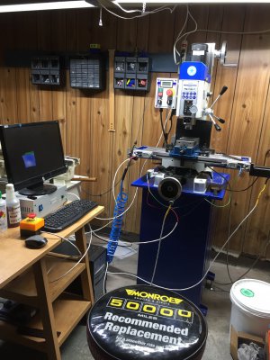
I have completed the first phase of my CNC conversion. I had a couple questions in another thread, but didn’t receive any feedback so I started a new thread to hopefully get a few answers and some feedback.
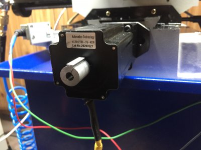
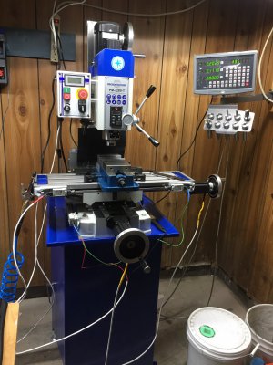
First, a little bit about my setup. It’s a pm-728vt with PM’s CNC kit. G540 running Mach3 on an old desktop using the parallel port. Right now it’s only 2axis with 570oz dual shaft steppers with a sepraty DRO.
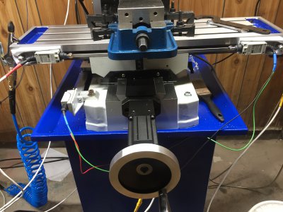
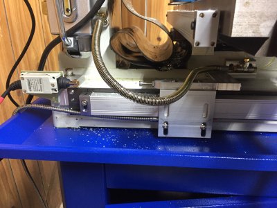
I’m happy with the CNC kit and can say the cast iron mounts were worth the 8 month wait. Everything bolted up as it should with no issues so far. I have about .0009 backlash in X and .0026 in Y. X is acceptable to me but Y seems like a lot. I tightened the lock nut till I had maybe .0001 axial play on the shaft end. So my question is can I or should I try to shim in between the double ball nut? Is it possible to have that much play in the shaft coupler? What else can I do to improve this?... as I’m typing, I realized I can swap the couplers to check there...
Also, in Mach 3 is there a way to use my homing switch as a limit switch or do I need to have two limits and a home switch for my x and y.
Overall I’m pleased with the machine, the only complaint I have is the Y axis ballscrew is not left hand thread. So since I tried to keep my hand wheels the table moves opposite as it normally would cranking it. And hopefully I can improve the backlash of the Y axis some.
Here’s a couple pics. Short term changes are going to be upgrading to Mach4. Installing the Z axis. I struggle to get fusion360 to post toolpaths with zero Z moves. ( I kind of wanted to have it like the 2 axis mill power setup I use at work and since I mainly have been running wire edm for the last 10 years. Z moves cause me anxiety. Lol.) Also need to clean up the wiring and start planning a partial enclosure.
Thanks for any feedback in advance.
First, a little bit about my setup. It’s a pm-728vt with PM’s CNC kit. G540 running Mach3 on an old desktop using the parallel port. Right now it’s only 2axis with 570oz dual shaft steppers with a sepraty DRO.
I’m happy with the CNC kit and can say the cast iron mounts were worth the 8 month wait. Everything bolted up as it should with no issues so far. I have about .0009 backlash in X and .0026 in Y. X is acceptable to me but Y seems like a lot. I tightened the lock nut till I had maybe .0001 axial play on the shaft end. So my question is can I or should I try to shim in between the double ball nut? Is it possible to have that much play in the shaft coupler? What else can I do to improve this?... as I’m typing, I realized I can swap the couplers to check there...
Also, in Mach 3 is there a way to use my homing switch as a limit switch or do I need to have two limits and a home switch for my x and y.
Overall I’m pleased with the machine, the only complaint I have is the Y axis ballscrew is not left hand thread. So since I tried to keep my hand wheels the table moves opposite as it normally would cranking it. And hopefully I can improve the backlash of the Y axis some.
Here’s a couple pics. Short term changes are going to be upgrading to Mach4. Installing the Z axis. I struggle to get fusion360 to post toolpaths with zero Z moves. ( I kind of wanted to have it like the 2 axis mill power setup I use at work and since I mainly have been running wire edm for the last 10 years. Z moves cause me anxiety. Lol.) Also need to clean up the wiring and start planning a partial enclosure.
Thanks for any feedback in advance.
Attachments
-
 302D5DE4-C36F-4401-A3AD-0AEB5ADC3FC2.jpeg1.1 MB · Views: 398
 -
 787FBF4E-B91F-4BF5-BC6D-BAC57CF6BA80.jpeg2 MB · Views: 376
 -
 6DBE071F-DDFE-40B3-BC78-B6963BA2FC8E.jpeg1.7 MB · Views: 352
 -
 AC8B1904-1462-49EF-8792-F28599A5EA4B.jpeg2.1 MB · Views: 357
 -
 E00B73BC-C2CB-4766-A824-A2C1C35AF5FC.jpeg1 MB · Views: 374
") )
)


