CLausing to VFD wiring help

gaston

Active User
Registered
Joined
Aug 4, 2011
Messages
69
Hi guys
Here is a problem I hope those who are well versed in the art of making electrify do what they want it to do. I would like to hook the newly acquired Clausing / Colchester VS 12” up to a Hunghang VFD.
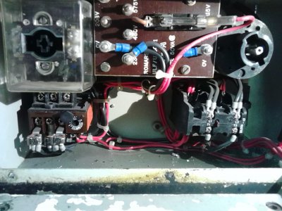
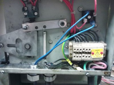
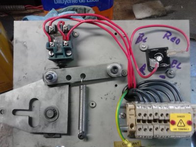
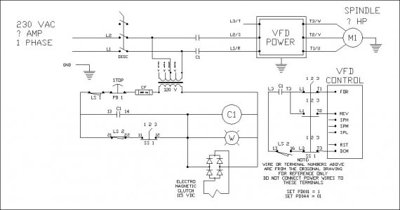
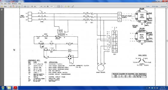
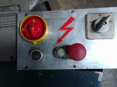
I am including a wiring diagram and pic’s of the electric components.
I want to be able to use the front panel controls on the lathe to run it, I know, no sweat just trash all the wiring and wire the control wires from the VFD to the switches. (like I did on my Vorest Lathe.
I need to use the transformer and some of the “other stuff” to control the electric clutch (110v dc from the transformer), the E switch and darn if I know what else.
I assume (dangerous word) I will need to hook up the 220 1phase to the “off-on” switch and then to the VFD but I’m lost from there.
Any help out there??
lathe wiring.jpg 2014-10-25 12.24.09.jpg 2014-10-15 15.49.22.jpg 2014-10-15 15.50.22.jpg 2014-10-26 13.22.49.jpg
 
I see view and so far no replies. I can tell you a few things for do's and do-not's from this site? And I'll offer some general items from my perspective. I'm NOT an expert but do have an EET background.
Do Do Not- http://machinedesign.com/motorsdrive...fd-right-power
See the do-not note about 1 line break on the VFD input line. I found out the hard way my used mill wired up w/ a 1 leg stop switch and it did blow it up. anyway- For starters the Do's and Do-not's was a good read.

As for the DC clutch. The Schemo you provided offers the DC power via a Bridge Rectifier setup from the source input. It's all setup and should only require your power input right? I'm new to the machine world but did work w/ relay logic (ladder logic) contactors and then into Linear Supplies and beyond. What you are looking to do can be component dangerous. If you are not too sure on some of this, I would think a good AC motor repair shop could do it for you???

It sounds to me as if you are looking to have the Main panel do what it currently does.
And get the VFD input into the loop. Thus you have a power routing issue more or less there.
Determine motor connection via VFD outputs. On the motor block.


To me it's always a list manner.
- Power input. Determine 220 1 phase input. and new 220 input for VFD via Panel. Should turn on power to both DC clutch circuit and VFD input?
-VFD motor output. Wire into the motor wire block junction assy? The VFD motor outputs should wire directly to motor source and No contactor or fuses (per do/do not) article. The VFD controls the rotation via the keypad.


Anyway- Others here are smarter than I on the machine controls and how to make this easier that it sounds. Looking forward to a few replies.
 
This would be a pretty simple install if it were not for the magnetic clutch in the circuit. I'm working on a circuit that will use your existing hardware, and keep the functionality the same as it is. The challenge is separating 120V control circuit for the clutch, and the 24V control circuit on the VFD without adding any parts. I think the key here is to use the relay output on the VFD to operate the clutch. I assume that you are going to use a Hunghang VFD so I'll work from that manual.

The diagram you supplied seems to show the motor running continuously and the spindle ON/OFF is controlled by the magnetic clutch, is this correct?


Jim, I'll pose this as a question???

Looks to me like the clutch is for stopping the spindle. I'd suggest disabling that and install a large VFD brake resistor. Now you got a simple system and rapid stops. just my two cents. I'd know more if I seen this machine up close and personal.

Karl
 
Karl, I agree. If the drawing said Electro Magnetic Brake there would not be any question.

The way I read the drawing is:

LS2 - 21,22 close, which is mechanically activated by the run lever
SS1 - 11,12 close in either FOR or REV (Center open)
this energizes C1, which is then sealed in by C1 - 13,14. This forces the Clutch to be de-energized on motor start.

Then by moving the lever to the run position, LS2 - 21,22 open, and LS2 - 13,16 close, thus energizing the Mag Clutch

The really odd thing I see here is that it looks like you could turn the motor off by switching SS1 to the center position, but C1 is still sealed in until you push the stop button, and the Mag Clutch is still energized if you don't change the position of the run lever. This would allow for an instant reverse via SS1.

Let me know if you see a flaw in my logic, it's always good to have a second set of eyes on the problem.
 
You're more EE than I. Surely, this thing drops the motor and hits the brake when power is dropped to it. I'd have to see it or interview an operator to be sure.

If this is correct, VFDs don't like sudden overloads. Just askin' for trouble.

BTW, if this is correct wire the clutch to the Estop. Always power it except when the easy stop is hit.

karl
 
Last edited:
You're more EE than I. Surely, this thing drops the motor and hits the brake when power is dropped to it. I'd have to see it or interview an operator to be sure.

If this is correct, VFDs don't like sudden overloads. Just askin' for trouble.

BTW, if this is correct wire the clutch to the Estop. Always power it except when the easy stop is hit.

karl

Karl, now ya done it, you made me change my drawing.:lmao:

OK gaston, I'm pretty sure this will work just like the old system, except the clutch won't disengage until you hit the E-stop button. The VFD will control FOR/REV and STOP.

SCHEMATIC.jpg

I hope this makes sense. I'll be around to answer any questions.

SCHEMATIC.jpg
 
Haven't had time to follow the wiring diagram, BUT the lathe just free wheels unless the clutch is engaged. there is a mechanical brake that is engaged by the linkage that trips the microswitch ie hit the brake - the clutch drops off and the brake pad is pushed against a pulley to stop the lathe. I don't know what happens if you move the f/r to the center off position, but I assume it trips the clutch, and the lathe coasts down unless you use the brake, then the F-off-R switch changes motor direction and reingages the clutch when moved off the "off" position.
I'll try to understand the wiring diagram tonight and hopefully gain some understanding . AS I mentioned, when it comes to electricity I'm a plumber
I really thank you guys for all the help I sure need it!
 
Karl, now ya done it, you made me change my drawing.:lmao:


I was a manufacturing engineer for many years. Job 1 was keeping the EEs in line. :)

karl

PS, Get it running first, but I really recommend brake resistors. IMHO, leaving a lathe coast to a stop is dangerous. If you're as cheap as me, find the ohms and watts, then surf eBay for one close. You can combine resistors in parallel and/or series to get the watts and ohms you need.
 
Back
Top