Clausing 8530 Restoration

Looking great! Hey find out how to weld steel to an aluminum hand knob, will you?

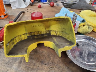
Thanks! I think it's a steel nut brazed to the aluminum knob using SMAW process. I thought the knob was steel till I put it in the caustic bluing tank. That got exciting real quick! The tank started to bubble like crazy, it looked like it was going to boil over, I knew something was wrong immediately. I took a few steps back to assess the situation. Decided to unplugged the burner, but that didnt help. The bubbles kept increasing, then finally it dawned on me to pull the part out of the tank. It was probably only in there about one minute and there's a ton of pitting where the caustic solution was violently attacking the aluminum. No photos before paint, but the pitting is still apparent despite my heavy handed paint job. I'm pretty sure that nut is going to snap off of there as soon as any torque is applied, the brazing is undercut pretty bad where the aluminum dissolved out from under it.
20230604_144219.jpg

I think that plate is gonna be a ***** to remove the red paint and preserve the underlying paint. You could order a replica? Someone here posted a resource. I wonder if thermal cycling could flake off the red?

I'd love to know about the source for replica plates, I've got a few machines that could use new plates. I have thought about how to make my own replica plates. When the original plate isn't covered in paint, I could scan it or take a photo, use that as a guide for creating new graphics, and print them on a clear sticker using my Laserjet printer. Then it would just be a matter of whipping up a little aluminum plate and slapping the sticker on there. It's been a while since I used Photoshop or illustrator but I could figure it out.

Anyhow, I did manage to get the spindle speeds plate clean today! I gave it a ~1min bath in the ultrasonic cleaner full of hot Simple Green Extreme, this softened the red paint, then I scraped it off with a plastic razor blade. It took a few cycles of this, but eventually the paint came off. I'm pretty surprised it came out as well as it did.
20230610_200502.jpg

I'm planning on running a batch of parts through the bluing tank tomorrow so I'll toss in the drive screws for the nameplate, then get it mounted back on the belt guard.
 
Got my clutch on the power feed calibrated. I ended up making a tool out of something I found in the bolt bin, it looked like the threaded part of a c-clamp or 3-jaw puller. It was turned down to the diameter of the lead screw (or ID of the clutch hub) then a slot cut in it with a #3 woodruff key cutter.

20230610_193737.jpg

At first I wasn't able to get the clutch calibrated, it would slip too easily then I'd tighten it up just a smidgen and it would be too tight. I decided that the oil on the fiber washers was messing with me, so I disassembled, degreased everything, blued the steel bits, and reassembled.

20230613_163939.jpg

There's a hole on the collar of the clutch assembly which allows an adjustable pin spanner with 1/8" pin to tighten the collar onto the hub. With a box wrench on my tool and the pin spanner on the collar, I was able to tighten down the clutch. Then with the gear clamped in the vice (with 3D printed plastic jaws) I was able to test the point where the clutch began to slip using a torque wrench to turn my tool. I initially targeted 24 in-lb, then increased to the final target (per the manual) of 36 in-lb. Eventually I got it to the point the wrench clicked just as the hub began to spin.

20230613_163804.jpg

Here it is installed back on the leadscrew, I should have a nut to secure it, but I lost it or more likely the machine didn't come with one. The clutch fits really tight on the screw, but I'll try to remember to get a acorn nut to go on there, just to be sure it won't come loose. After the photo was taken a dab of the Lucas red-n-tacky #2 lithium grease was applied to the clutch gear.

20230613_164741.jpg

Bonus shots of the power feed while I had it off...
20230613_164804.jpg
20230613_164811.jpg
20230613_164817.jpg
 
Here's some shots of the head prior to disassembly.
20230602_163249.jpg20230602_163300.jpg
Gotta wonder what the last guy was thinking when he decided to paint the machine silver, the belt guard yellow, the handles red, then for the finishing touch, he paints only the screws for the belt guard, green.
20230602_163321.jpg

20230602_163431.jpg
20230528_160207.jpg
 
Last edited:
The downfeed lever was rusted in place and didn't want to come off without a little help from my creepy friend Kroil and some careful pry bar action.20230602_164941.jpg

Tappy tap tapped those little drive screws out of the nameplate. This is one of the few spots the original paint was still visable. I think the smoke gray I'm using is a bit lighter than the original, but hey it's convenient and close enough.

20230602_170421.jpg

I decided to mount the head on the machine at this point, so that I wasn't wrestling it around on the bench. Couple of SHCS come out of the plate atop the pulley. Then I had to file some burrs off the splines on the spindle so that the plate would slide up and off. I have no idea how someone manged to gouge up the splines.
20230609_152027.jpg
20230609_152607.jpg

Oh this doesn't look good... Once the plate come off, there's lots of rust on the upper pulley bearing. The snap ring which retains the pulley has been removed at this point.
20230609_152611.jpg

A few whacks with a dead blow hammer did nothing to budge to pulley, so the 8" three jaw puller was called into play.

20230609_153547.jpg

Once the pulley was removed, the bottom side of that upper bearing was visable for inspection, not quite so rusty underneath. Note there's two snap rings to separate to upper and lower pulley bearings, the lower bearing remained stuck on the pulley sleeve assembly.
20230609_153720.jpg

There was a weird fiber washer atop to upper bearing, but below the snap ring, not sure it's purpose. It's not pictured on the parts diagram.
20230609_153735.jpg

Here's the pulley sleeve with the lower bearing stuck on it.
20230609_153909.jpg

Removed three SHCS from the pulley sleeve and pulled it off by hand. Lots of rust visible on the top of the upper spindle bearing and the top end of the quill.
20230609_154246.jpg
 

Attachments

  • 20230602_170432.jpg
    20230602_170432.jpg
    596.3 KB · Views: 5
Time to take a peek at those fine downfeed gears to see if they're damaged, as they so often are...
20230609_154345.jpg
20230609_154519.jpg

Looks good, nothing obviously broken.
20230609_154534.jpg

On closer inspection there's some pretty bad wear on this little guy. Might have to look into a replacement if the backlash is too severe.
20230609_154633.jpg
 
I got the SPA-1 from Park Tool to unscrew the seal retainer from the quil, it worked quite well, luckily it wasn't on there too tight.
20230609_155003.jpg

A few good whacks on the top of the spindle with my small dead blow hammer and the spindle was free from the quill.

20230609_155850.jpg

Interestingly, the upper spindle bearing came out with the spindle. I was expecting it to remain in the quill and need to be extracted separately.
20230609_160422.jpg

For reference purposes the upper spindle bearing was a MRC 204 SFF. Luckily the bottom side wasn't as rusty as the top so i was able to snag this shot of the P/N. I'm replacing it with the Timken 6204-ZZ Shown above.
20230609_160333.jpg

A bearing splitter was used to grab the upper spindle bearing below the inner race and pull it up off of the spindle. A scrap of aluminum was placed atop the spindle to keep the bearing separator from damaging it.
20230609_161427.jpg

The lock washer tab was pried out from the nut that is used to preload the lower spindle bearings. Then a pin spanner wrench was used to loosen the nut.

20230609_162301.jpg
20230609_162248.jpg

The extensions that came with my bearing separator were not long enough to pull the lower spindle bearings off the spindle. Custom extensions were fabricated out of all-thread rod, to get enough length to grip under the bearings.
20230609_173153.jpg

You can see the bearing separator was just catching the inner race, but not gouging into the spindle. I'm always a bit nervous about torquing this separator around a shaft and causing damage. The edge of this Pittsburgh Automotive brand bearing separator is not very sharp so it can be difficult to get it into a narrow gap between the bearing and a shoulder, such as we have here. I would sharpen the edge, but I'm concerned that the thinned out edge would just get bent up in situations where it can only just grab the edge of the inner race.
20230609_173530.jpg

The spindle bearings had some pretty nasty looking grease in them.
20230609_174133.jpg

While we got the bearing separator out, might as well circle back and pull that lower pulley bearing off the sleeve. Note, a socket was used as a spacer to pull the bearing completely free of the sleeve.
20230610_094412.jpg

The depth stop was removed to allow the quill to come out of the head.
20230610_100035.jpg
20230610_100038.jpg

...And there you have it, a box full of 8530 head, some cleaning, derusting, and finishing required.
20230610_100601.jpg
 
Last edited:
Here's a photo of post degreasing and evaporust soak of the quill, spindle brake ring & handle, spindle, lock washer, nut, seal retainer.


20230611_143858.jpg

A fine deburring wheel/finishing wheel, of the non-woven variety, was used to clean up the spindle, seal retainer and nut. On the spindle the bearing mating surfaces were avoided to keep them dimensionally accurate.
20230611_183608.jpg

I did go through and use an aggressive cutting compound and sewn wheel to polish the non-bearing surfaces of the spindle and the seal retainer. Then polish and finishing compounds were used with less aggressive wheels to give everything a nice shine, including the quill and even the bearing surfaces. They're visible in later pictures to come, but I'm trying to keep the time-line in tack here.

Here's all the other hardware after bluing and oil coating.
20230611_183613.jpg

The original bearings spent a few day soaking in the Stoddard solvent tank out back. I decided for now to just go ahead and use them. Mostly just because I couldn't decide what to replace them with, but also because they were very smooth once cleaned up. I can always swap them out if they give me any trouble. Anyone know if the Fafnir 205K C1 are actually original equipment? It doesn't seem like this machine has even been torn down, but you never know what happened in this machine's previous life.
20230616_191518.jpg
 
Back
Top