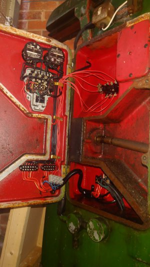
Can anyone tell me what this is?

Is there still a separate pump switch on the panel? I'm wondering if the pump is set up to run whenever the lathe motor is running?
 
Last edited:
Is there still a separate pump switch on the panel? I'm wondering if the pump is set up to run whenever the lathe motor is running?
Yep. Its a Mill but same theory.

I have tested the operation and in short, forward or reverse is selected for the motor on the front panel, separate switch next to it for coolant, on or off.

Power is activated to both by a knee mounted no-volt switch. The pump runs only when a motor direction is selected and the coolant pump is switched on.
 
The arrowed bit looks like the reversing switch shown in the schematic above the contactor.
It looks as though it had been broken off and remounted
 
The arrowed bit looks like the reversing switch shown in the schematic above the contactor.
It looks as though it had been broken off and remounted
Understood. I will go back and trace the cabling again, I thought that this was in the power feed to the coolant pump not the motor but now i'm doubting myself...:rolleyes:
 
On the schematic notice the numbers and letters many can be seen on your picture.
A, B ,C, L1,L2,L3 also note the colors on the switches can be traced back to those on the drawing from the contactor terminal strip, the clues are there...
 
Understood. I will go back and trace the cabling again, I thought that this was in the power feed to the coolant pump not the motor but now i'm doubting myself...:rolleyes:

Tricky to see from the picture but its definitely in the feed to the pump. This picture shows the two connector blocks in the schematic. all cables are correctly wired. the left block has 3 phase lines in and the return to the switch on the knee. correct colour wires. The right block hs three larger guage reds that feed to the motor.

The 3 that are in slots 4,5+6 on the right block (on the door) are red, thinner and run up to the 'mystery' component and back down to that 'new' connector. the 3 blue wires are all phases and lead to the pump...

Ignore the block on the main body of the machine on the right, its just bringing in power and linking back to the motor. probably to save the cable strain?

I'm leaning towards 'secondary' contactor

2023-07-04 07.34.53.JPG
 
With the new picture it looks like the blue arrow component is the coolant contactor and there is an overload adjustment on the right side a small white projection with a screw driver slot.
I like to make a copy of the schematics so I can write notes or even color with Hi lighters for easier tracing. Good luck
 
Back
Top