Building clutch

I saw this diagram for a single-plate clutch and am building it. From the diagram it looks like the withdrawal sleeve is part of the pressure plate. How then is the clutch fork mounted so that it doesn't rotate? If the sleeve is separate from the plate how does it act to retract the plate? I'm thinking I might need some kind of thrust bearing as well?
Any ideas?

What you are looking at is a pull clutch, instead of pushing on the fingers you pull. This is same as in the 90's Corvettes with LT1 due to the lack of room to put the slave cyl. On this system the Throwout bearing or thrust bearing is on the inside of the pressure plate not the best idea but it works. They are a lot of fun to change I did mine the beginning of last year in a 92.

Todd
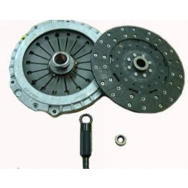
36857.jpg
 
I saw this diagram for a single-plate clutch and am building it. From the diagram it looks like the withdrawal sleeve is part of the pressure plate. How then is the clutch fork mounted so that it doesn't rotate? If the sleeve is separate from the plate how does it act to retract the plate? I'm thinking I might need some kind of thrust bearing as well?
Any ideas?

Just out of curosity, what are you buillding it for and where did you get the diagram and such?
 
Just out of curosity, what are you buillding it for and where did you get the diagram and such?

The diagram is from Hilliers Fundamentals of Motor Vehicle Technology. I found it in Google Books.
I thought it would make a good learning project on the lathe. It looked simple enough and I could test it with a DC motor. I thought I might use it as a clutch for a lathe I am building. Just thought it would be fun to build and test. I have a bench top lathe and several drill presses, an inexpensive source for steel and a lot of time on my hands to work in my shop so I'll try anything I can make with the equipment I have.
btw: thanks for the response.
 
Back
Top