Building clutch

Billk

Active User
Registered
Joined
Dec 27, 2013
Messages
27
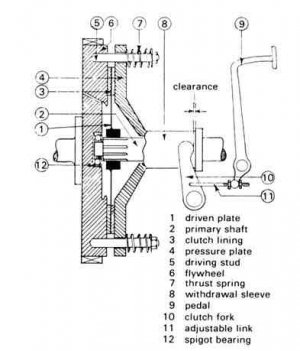
I saw this diagram for a single-plate clutch and am building it. From the diagram it looks like the withdrawal sleeve is part of the pressure plate. How then is the clutch fork mounted so that it doesn't rotate? If the sleeve is separate from the plate how does it act to retract the plate? I'm thinking I might need some kind of thrust bearing as well?
Any ideas?

image.jpg
 
Generally speaking, that diagram is a bit backwards, at least when thinking of Automotive clutches. An automotive clutch usually has a pressure plate that compresses the clutch disc between the pressure plate and the flywheel with spring pressure. The levers that release the pressure are usually activated by pushing a release , or "throwout" bearing toward the flywheel. The pressure plate is designed so that this releases the compression allowing the clutch disc to turn freely. The throwout bearing is usually activated by a fork on a fixed pivot point. That diagram would require the sleeve to be pulled away from the flywheel to release the pressure. To answer your original question, yes the release sleeve would need some sort of thrust bearing that would allow the sleeve to rotate with the clutch and transfer the release pressure from the fixed release fork to the rotating pressure plate.
 
Generally speaking, that diagram is a bit backwards, at least when thinking of Automotive clutches. An automotive clutch usually has a pressure plate that compresses the clutch disc between the pressure plate and the flywheel with spring pressure. The levers that release the pressure are usually activated by pushing a release , or "throwout" bearing toward the flywheel. The pressure plate is designed so that this releases the compression allowing the clutch disc to turn freely. The throwout bearing is usually activated by a fork on a fixed pivot point. That diagram would require the sleeve to be pulled away from the flywheel to release the pressure. To answer your original question, yes the release sleeve would need some sort of thrust bearing that would allow the sleeve to rotate with the clutch and transfer the release pressure from the fixed release fork to the rotating pressure plate.

Looks to me as though the back of the fork is supposed to simply run against that flange on the spinning sleeve. I think that would wear pretty fast. I'd add a throwout bearing assembly pinned to the fork.
 
Years ago I had a old cat track loader that had a clutch that worked like that.it was a hand clutch. Push forward it would snap in engaging the driveline. Pull back it would pull pressure plate back . I know this because a big snap ring on rear of pressure plate broke. This left you with clutch engaged and no way to disengage it.

Scruffy
 
From what I can make out the throwout fork doesn't touch anything until the pedal is depressed to disengage the clutch.
No contact, no wear.
 
From what I can make out the throwout fork doesn't touch anything until the pedal is depressed to disengage the clutch.
No contact, no wear.

No wear while the clutch is engaged, but plenty every time you step on the pedal and push the fork against the spinning flange. Ok for very light duty, I suppose.
 
To me there is no way that this clutch would work properly. The springs would force at least the outer edge of what is labeled pressure plate against the clutch disc all the time. When you would step on the pedal the fingers would roll the pressure plate away from the disc on the outer edges and in on the inner. They are missing the "shell " portion of pressure plate. If someone can explain how this would work as drawn I would appreciate it. I have seen many modern clutch discs and this drawing is missing important components.
 
To me there is no way that this clutch would work properly. The springs would force at least the outer edge of what is labeled pressure plate against the clutch disc all the time. When you would step on the pedal the fingers would roll the pressure plate away from the disc on the outer edges and in on the inner. They are missing the "shell " portion of pressure plate. If someone can explain how this would work as drawn I would appreciate it. I have seen many modern clutch discs and this drawing is missing important components.

What fingers? This clutch has none that I can see. As I read it the pressure plate and sleeve are all one piece. The fork pushes on the flange on the sleeve, pulling the entire pressure plate straight back against the springs. It's sort of a simplified textbook illustration of a clutch.
 
You are right John. I missed the way the linkage between the pedal and the "withdrawl sleeve " would operate. :whistle:There would have to be a "connection between the pressure plate and the withdrawl sleeve that must be somewhat indicated be the wavy end to the withdrawl sleeve. I guess I am used to the standard muscle car/ light truck clutch's operate. This one operates in reverse as SEK mentioned.
I would think that a bearing would still be best between the withdrawl sleeve and the fork as John stated.
 
Ball bearings on the ends of the clutch fork tines that would ride against the flange of the withdrawal sleeve when the clutch is disengaged might make it a little better.

By the way, What is the intended purpose of this clutch?
 
Last edited:
Back
Top