- Joined
- Jun 26, 2013
- Messages
- 191
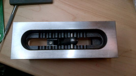
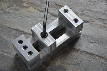
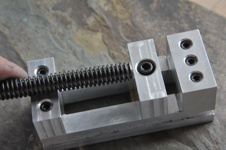
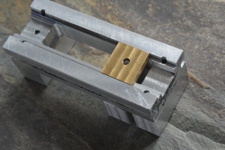
So I've decided I'm going to build me a small "screwless" machinist vise. I know I could just buy one for fairly cheap that would be a lot better than what I can build in terms of precision, hardness, surface finish, etc - but I decided, what the heck, I'll give it a go anyway. If I screw it up, I can always just buy a replacement...
I know this wouldn't be a challenge for many of the members here, as I'm definitely in the beginner camp, but figured I'd share the process anyway. I know I'll have questions (already have) and who knows maybe it'll help someone else out at some point... Anyway, here goes...
I started with some plans from another site for a small machinist vise. On a whim I had also bought some 1x1.5 12L14 bar off ebay, so I figured I use that. The plans had the base and fixed jaw of the vise machined out of a single hunk of steel. Just given the size of the bar I had to work with, I was going to need to make the fixed jaw out of a separate piece. Here was my original idea:
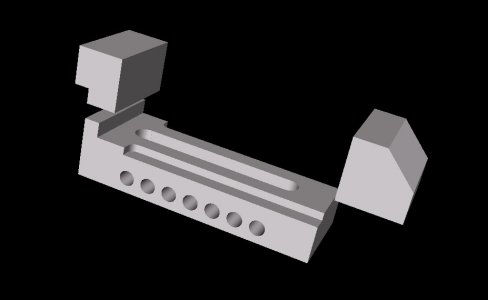
BTW - another post on this site turned me on to the eMachineShop design software - very cool, very easy tool...
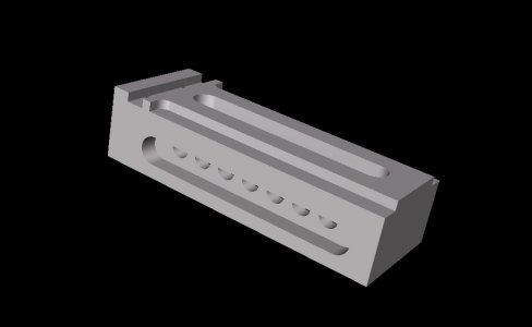
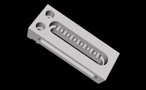
Anyway, I figured the step in the back of the fixed jaw would help to lock it into position, then a couple of cap screws would secure it to the base. I've since changed the design and replaced that step with a groove and a matching tenon on the fixed jaw to lock them together (see next pic). That change allowed me to keep the full 1" thickness of the base. I've also been toying with various arrangements for the adjusting bar (which the movable jaw pulls against). Definitely haven't settled on a design for that yet. In this pic I've got a different approach for the adjusting bar which wouldn't require completely removing it to adjust the opening.
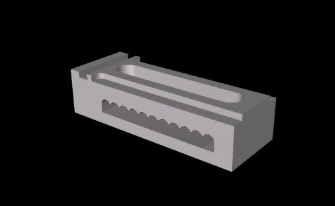
I am a little concerned that this approach removes too much metal from the base and may introduce too much flexing? With this approach the base basically becomes a hollow box with four 1/2"x1/4" legs. I'm sure it would be plenty strong/stiff for what I need, just wondering if there may be a better compromise...
Enough with the design, on to starting the build...
I began with a slighter longer than 6 inch section of the 1x1.5 bar, supposedly 12L14...
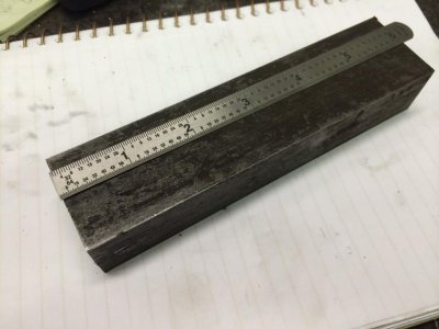
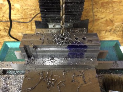
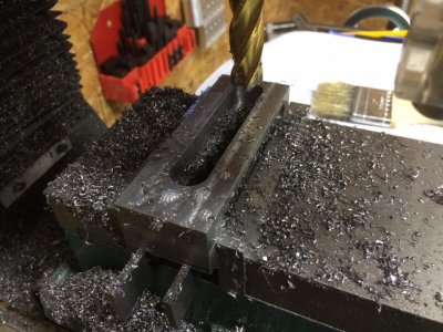
I set to squaring it up on my mill (G0704):
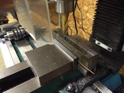
This is when I began to suspect that it wasn't really 12L14. I've used 12L14 on my lathe before and it always turned and cut like butter. This stuff cut like, well, steel. Not sure what it actually is, but I'm pretty sure it's not 12L14...
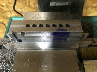
All cleaned up:
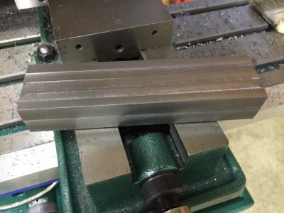
I then cut the jaws from this piece and squared up all the ends:
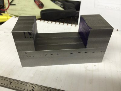
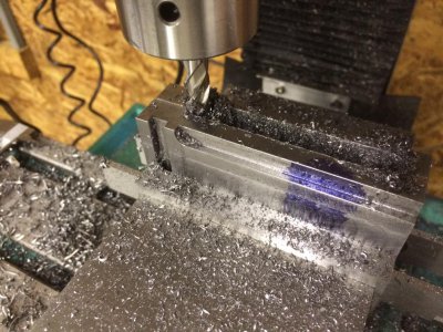
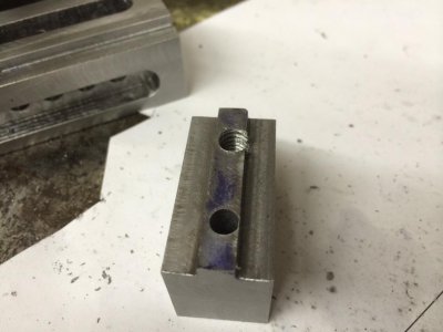
Here's the slot in the base, with the tenon on the fixed jaw fitted:
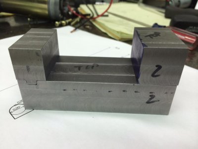
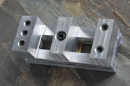
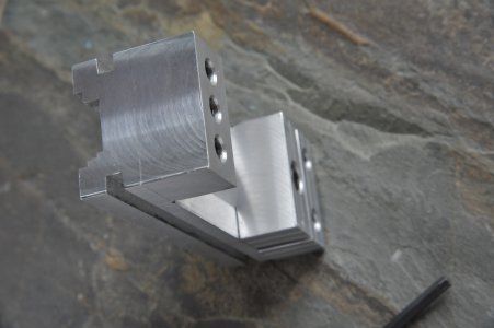
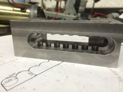
I had some DRO issues while laying out and cutting the slot and tenon, so the back of the jaw isn't flush with the back of the base. But that won't hurt anything. I also had some fitment issues with the tenon. The inside corners of are not getting milled out cleanly. It's like the end mill has a very slight radius at the edges, so the inside corners are very slightly rounded. To fit the fixed jaw I ended up relieving the outside corners slightly with a file. Would this be considered normal? The plan I got for the vise (and an actual manufactured screwless vise I have) have relief cuts on the inside corners, almost as if the corner was drilled out prior to be milled. Is there a trick to this that I'm missing? Any pointers would be welcome. Relieving the outside corners was fine for that piece, but I've got a similar issue with the slots and groove I cut for the movable jaw:
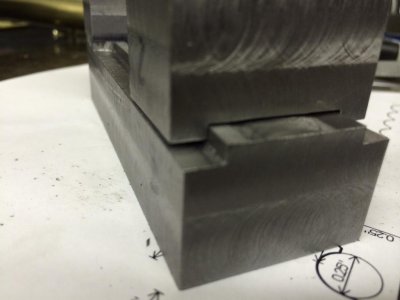
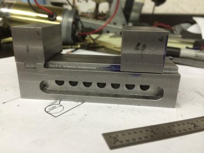
Before I bevel the outside corners here, thought I would ask for suggestions on ways to relieve the inside corners...
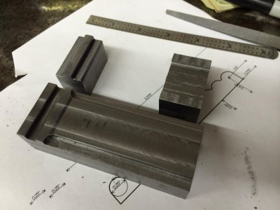
I'm happier with the fit of the movable jaw, it has just a few thousands clearance and has no noticeable "play". Other than the fact it doesn't sit all the way down, it slides and fits quite well.
Anyway, this is as far as I've gotten so far. Hope this doesn't bore anyone to tears...


I know this wouldn't be a challenge for many of the members here, as I'm definitely in the beginner camp, but figured I'd share the process anyway. I know I'll have questions (already have) and who knows maybe it'll help someone else out at some point... Anyway, here goes...
I started with some plans from another site for a small machinist vise. On a whim I had also bought some 1x1.5 12L14 bar off ebay, so I figured I use that. The plans had the base and fixed jaw of the vise machined out of a single hunk of steel. Just given the size of the bar I had to work with, I was going to need to make the fixed jaw out of a separate piece. Here was my original idea:

BTW - another post on this site turned me on to the eMachineShop design software - very cool, very easy tool...
Anyway, I figured the step in the back of the fixed jaw would help to lock it into position, then a couple of cap screws would secure it to the base. I've since changed the design and replaced that step with a groove and a matching tenon on the fixed jaw to lock them together (see next pic). That change allowed me to keep the full 1" thickness of the base. I've also been toying with various arrangements for the adjusting bar (which the movable jaw pulls against). Definitely haven't settled on a design for that yet. In this pic I've got a different approach for the adjusting bar which wouldn't require completely removing it to adjust the opening.

I am a little concerned that this approach removes too much metal from the base and may introduce too much flexing? With this approach the base basically becomes a hollow box with four 1/2"x1/4" legs. I'm sure it would be plenty strong/stiff for what I need, just wondering if there may be a better compromise...
Enough with the design, on to starting the build...
I began with a slighter longer than 6 inch section of the 1x1.5 bar, supposedly 12L14...

I set to squaring it up on my mill (G0704):

This is when I began to suspect that it wasn't really 12L14. I've used 12L14 on my lathe before and it always turned and cut like butter. This stuff cut like, well, steel. Not sure what it actually is, but I'm pretty sure it's not 12L14...
All cleaned up:

I then cut the jaws from this piece and squared up all the ends:

Here's the slot in the base, with the tenon on the fixed jaw fitted:

I had some DRO issues while laying out and cutting the slot and tenon, so the back of the jaw isn't flush with the back of the base. But that won't hurt anything. I also had some fitment issues with the tenon. The inside corners of are not getting milled out cleanly. It's like the end mill has a very slight radius at the edges, so the inside corners are very slightly rounded. To fit the fixed jaw I ended up relieving the outside corners slightly with a file. Would this be considered normal? The plan I got for the vise (and an actual manufactured screwless vise I have) have relief cuts on the inside corners, almost as if the corner was drilled out prior to be milled. Is there a trick to this that I'm missing? Any pointers would be welcome. Relieving the outside corners was fine for that piece, but I've got a similar issue with the slots and groove I cut for the movable jaw:

Before I bevel the outside corners here, thought I would ask for suggestions on ways to relieve the inside corners...
I'm happier with the fit of the movable jaw, it has just a few thousands clearance and has no noticeable "play". Other than the fact it doesn't sit all the way down, it slides and fits quite well.
Anyway, this is as far as I've gotten so far. Hope this doesn't bore anyone to tears...


Last edited:


