Yes, you're right. To make your shim, you want to use a fly cutter so the surface is created in just ONE pass.
OK, that makes sense but I am afraid my toy mill does not have enough power to drive a fly cutter that big .....

Yes, you're right. To make your shim, you want to use a fly cutter so the surface is created in just ONE pass.
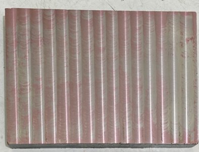
OK, I tried again with the following changes :
1) a much shallower depth of cut - 0.03 mm
2) reduce the overlapping between adjacent passes to 0.5 mm
3) use cutting oil
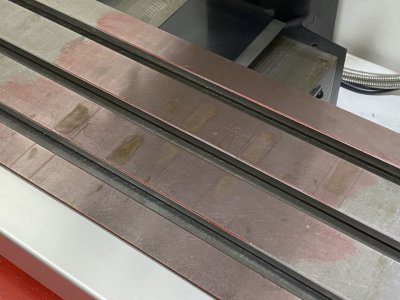
The finish is a lot better although my major concern is still on the flatness of the surface. The only flat surface reference I have got is the mill table so checked by inking the table surface and rub the workpiece against it. The result shows that :
1) the workpiece is basically flat over the majority of the area except for the part on the right. May be the mill table was moved so much to the left that the weight of the table plus the power feed unit on that side tilted to table so this part of the workpiece was raised hence cut deeper ?
2) in each pass ( tool always moved from top to bottom of the workpiece ), the right side is always cut deeper by a very tiny amount. This is not consistent with the expeceted deflection direction of the tool so I think deflection was not happening. May be the X tram is still imperfect.
Another interesting thing learned in this work is that thermal expansion of the mill is really something requiring attention in high-precision work. In one of the attempts I milled the workpiece for only half of the area and went away for a beer before coming back to finish the rest. What I got was a step betwen the two areas. It can be clearly felt by hand and my DTI indicated that the height was about 0.005 mm. The cause is thermal expansion of the spindle. Then I redid it in one go and the step did not appear again.
Fly cutter is not an option for me because I don't have one and this work will require one with 120 mm diameter. Base on the awful experience of cutting stainless steel with a 40 mm facing head, I have some doubt if it will work on my small machine. Cutting aluminium is no problem though. I have got a 63 mm facing head which can produce very good finish on 6061.
Observation #2 suggests that your X tram is imperfect. But....is the "tiny amount" you referenced more than you can tolerate? How much will it actually impact the work that you to do? Maybe it's good enough as it is. From my own experience, it's all too easy to get sucked into making ever-finer adjustments to our machines rather than using them to make useful (or fun) things.OK, I tried again with the following changes :
1) a much shallower depth of cut - 0.03 mm
2) reduce the overlapping between adjacent passes to 0.5 mm
3) use cutting oil
The finish is a lot better although my major concern is still on the flatness of the surface. The only flat surface reference I have got is the mill table so checked by inking the table surface and rub the workpiece against it. The result shows that :
1) the workpiece is basically flat over the majority of the area except for the part on the right. May be the mill table was moved so much to the left that the weight of the table plus the power feed unit on that side tilted to table so this part of the workpiece was raised hence cut deeper ?
2) in each pass ( tool always moved from top to bottom of the workpiece ), the right side is always cut deeper by a very tiny amount. This is not consistent with the expeceted deflection direction of the tool so I think deflection was not happening. May be the X tram is still imperfect.
Another interesting thing learned in this work is that thermal expansion of the mill is really something requiring attention in high-precision work. In one of the attempts I milled the workpiece for only half of the area and went away for a beer before coming back to finish the rest. What I got was a step betwen the two areas. It can be clearly felt by hand and my DTI indicated that the height was about 0.005 mm. The cause is thermal expansion of the spindle. Then I redid it in one go and the step did not appear again.
Fly cutter is not an option for me because I don't have one and this work will require one with 120 mm diameter. Base on the awful experience of cutting stainless steel with a 40 mm facing head, I have some doubt if it will work on my small machine. Cutting aluminium is no problem though. I have got a 63 mm facing head which can produce very good finish on 6061.
")
When I'm machining something I always try to get as close as I can to the designed dimensions, even if they're not all that critical -- I view it as an opportunity to improve my abilities in that direction.