Basic question on face milling

compact8

Registered
Registered
Joined
Oct 13, 2012
Messages
324
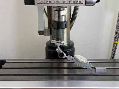
My Emco FB2 mill is out of tram by 0.05 mm over 150 mm along the Y axis. Negligible along the X axis ( adjustable ). I performed a face milling operation with the following parameters :

material : hot roll steel ( called "A3" by the vendor )
tool : 10 mm carbide end mill
rpm : 1100
travel direction of the tool : back and forth along the Y axis
cutting fluid : nil
depth of cut : 0.1 mm
overlapping between neighboring passes : 2 mm

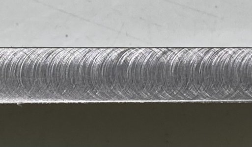
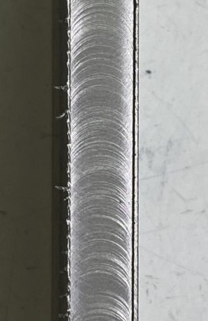
The result is shown in the photo. As expected, the machining marks are series of arcs instead of complete circles due to the imperfect tram but my question is not about the finish but the flatness of the surface.

As the tool is not perfectly perpendicular to the table, I would expect the tool to dig slightly deeper into the metal at the center so the surface cut out by each pass should be slightly concave having the two sides higher than the center. I checked that by inking the machined surface with a marker pen and rubbing the surface with the base of my vice ( should be very flat ) and the result indicates that the opposite is true, ie, the sides are lower ( ink not rubbed off ). Just wondering if I am missing something here. Any comments ?

What I am trying to do at the end is to make a wedge shim having the surfaces as flat as possible with my out-of-tram mill and subsequently use the shim to fix the misalignment problem ( more details in this thread ).
 

Attachments

  • IMG_6713.jpg
    IMG_6713.jpg
    243.4 KB · Views: 79
Last edited:
I may be misunderstanding this, but your picture and explanation shows the X axis is off. The black lines (sides) shows that the head is tilted a little off of perfect tram. Since the lines are in Y travel, the endmill is tilted left to right. If it was tilted in forward to back, you would have the dish you are expecting to see. You state that the Y tram is .05mm (.002) out over 150mm (5.9"). That actually is not bad for a small mill. My PM mill was way worst then that and I fought with it for two years before finally fixing it.
Here are some questions and points.
How are you measuring this? A car rotor (new) lightly secured to the table will show tram and you can rotate it to take any variance out of the measurement. I ditched this for a better way.
If you using a vise, find the sweet spot on the bed for it. The table is not always perfectly flat. Mine varied about .002 all over. I would tramm and shim the vise until it was perfect. I mean .0001 over 4 ". It was a Kurt D40. I would surface a block and it would be out .002, sometimes more over 3-4 ". I would shim the block with feeler gauges and rolling paper and sometimes it would work and other times it wouldn't.
I shimmed the column at first and then the vise to correct Y tram and it was a total failure.

Here is my solution to get about .0005 readings over 4-5", in both X &Y axis.
Mount your vise where you normally keep it. Make sure The table is stoned, gibs correct, column locked. All that kind of stuff. Center the vise under the spindle. Make a caveman tram out of a piece of bent rod (I used 1/2") and mount a DTI in the end. The length will be determined on what you need for the shortest side. I used a 2X4X6 block on each end to be taller then the vise and tramed the bed to .0002. Took about an hour and a lot of language. Watch Blondihacks to see this.

Make keys for your vise. This was the secret. The table was not perfect and tightening the vise down so it didn't move was distorting the vise clamping. Shimming the vise for perfection only made it worse. Making the keys allows the vise to go into perfect tram. Mine is .0002 over a 9" precision parallel clamped in the jaws, both X & Z. Clamping the vise in place now is just a little more then finger tight. Come to find out the Y tram was OK to begin with. If not some Zig Zag papers or a long feeler gauge can correct that.

I now clamp a block in the vise, tap it down and go for it. Everything comes out within .001, usually around .0003-4 over 3-4 inches which is the majority of my stuff.

Sorry about the long post. Hope this helps. Chewy
 
If the work and/or fly cutter are tilted, from the viewpoint of the work-surface plane the path of the cutter can look like an ellipse....depending on how the work is moved while cutting. If the column is tilted over a bit on the X axis and the work is moved along the X axis, the cutter will create a shallow groove -- basically, that section of ellipse that intersects the surface of the work. But what if the work is moved along the Y axis instead? In this case the cutter will cut a flat-bottomed slot, but it will be tilted.

So to create that shim of yours to correct head droop on Y you want to move the work along the X axis.
 
What I see::
a) the tool is deflecting under pressure far more than however far off tram the head is.
b) the major axis is moving too fast
c) the major axis is not moving at constant speed
 
a) the tool is deflecting under pressure far more than however far off tram the head is.

Didn't take into account deflection. Mitch has a real valid point. That may account for the lines, but doesn't fix the Y tram.
 
So to create that shim of yours to correct head droop on Y you want to move the work along the X axis.
I was thinking exactly along this line but my conclusion is that moving along the Y axis should create better result, ie , the surface will have less peak-to-valley distance. My machine has a droop along Y. The tool is touching the workpiece surface only on the operator's side. On the other side, it is 0.05 /150* 10 = 0.0033 mm above the surface. If I run the tool along X with zero overlapping between adjacent passes , the resulting surface will theoretically look like this :

1647229414270.png

If I move the tool along the Y axis, the magnitude of the ripple will be halved as depicted below. Again, this is very theoretical. Other factors such as tool deflection can lead to different results as I am seeing.

1647229443198.png


Is my understanding correct ?
 
Last edited:
How are you measuring this?

Two methods basically :
1) by sweeping a DTI over the table as shown in photo #1. The table surface has to be parallel to the X and Y rails for the method to work. Mine is close to perfect along the Y axis and just 0.008 mm over 200 mm along X, very acceptable for me.

2) I learned this from the forum - by checking the machining marks. The tram of my mill is acceptable along X ( 0.02 mm over 220 mm ). If facing is done with the tool moving along X, the machining marks are a series of arcs in both directions indicating that the tool is touching the workpiece surface on both sides ( photo #2 ). If the tool moves along Y, all the arcs are in one direction only ( photo #3 ).


Here is my solution to get about .0005 readings over 4-5", in both X &Y axis.
Mount your vise where you normally keep it. Make sure The table is stoned, gibs correct, column locked. All that kind of stuff. Center the vise under the spindle. Make a caveman tram out of a piece of bent rod (I used 1/2") and mount a DTI in the end. The length will be determined on what you need for the shortest side. I used a 2X4X6 block on each end to be taller then the vise and tramed the bed to .0002. Took about an hour and a lot of language. Watch Blondihacks to see this.

Make keys for your vise. This was the secret. The table was not perfect and tightening the vise down so it didn't move was distorting the vise clamping. Shimming the vise for perfection only made it worse. Making the keys allows the vise to go into perfect tram. Mine is .0002 over a 9" precision parallel clamped in the jaws, both X & Z. Clamping the vise in place now is just a little more then finger tight. Come to find out the Y tram was OK to begin with. If not some Zig Zag papers or a long feeler gauge can correct that.

I now clamp a block in the vise, tap it down and go for it. Everything comes out within .001, usually around .0003-4 over 3-4 inches which is the majority of my stuff.

Not sure if I have understood your method correctly but my understanding on spindle tram is about the perpendicularity of the spindle relative to the X and Y rails, not the table or vice surfaces so adjusting the tilt of the spindle need be done instead of working on the table or the vice ?
 

Attachments

  • checking tram.jpg
    checking tram.jpg
    91.8 KB · Views: 41
  • X axis.jpg
    X axis.jpg
    141.5 KB · Views: 32
  • Y axis.jpg
    Y axis.jpg
    49 KB · Views: 44
Last edited:
What I see::
a) the tool is deflecting under pressure far more than however far off tram the head is.
b) the major axis is moving too fast
c) the major axis is not moving at constant speed

a) is possible although the cut is very shallow ( 0.1 mm ), it is a carbide tool and the metal is on the soft side ( base on the sound and feel I got via the hand wheel ). I will try shallower cut and see the result.

b) and c) are correct as the feed was done manually but I think that should not be the cause of the overlapping area having lower height ?
 
Last edited:
Your pictures show better then your drawing what you have. I did a drawing to try and show better. My cuts were not quite that bad, but bad enough until I did what I told you. Last week when I used a 3" Shars face mill, my stock turned out mirror finish with .0007 deviation on all measurements across the face.
1. You have a small mill. Unless you never use a vise, the vise weight will affect it. Also resting your hand on the table or placing tools on it. If you had a 4000 lb Bridgeport, this would not be an issue.
2. Take your indicator and sweep the entire table left to right, all 3 faces and mark the reading every two inches (50mm). The bottom picture shows x's, what I mean. I suspect that your readings will be all over the place. My 30" table varied about .002 up and down all over the place, front to back and left to right. Just not real good manufacturing.
3. You show doing the tram on a little tiny piece of steel on the table. You are tramming that small spot. If you move the table several inches over, the tram will most likely change. If you place a flat piece of metal on the table, it will bridge over any deviations in the table and the tram will change. If you place a vise on the table, it too will bridge over and deviations and the tram will change. Try placing a new car rotor on the table in the same spot after you do it your way and see if your tram changes. The rotor will bridge over small deviations and give a better picture of relation of spindle to table tram.
4. Better still is to do what the top picture shows. Put everything on the table in normal position and check the tram over some distance. A .0001 reading over 4" can easily be several thousands out overall. Mine is .0002 over 14".
5. After you are done and put your vise on, use the DTI to dial in the vise bed to perfect .0001 side to side and front to back. May need a rolling paper or .001 feeler gauge under the end to get there. Tighten down the vise around finger tight and try the cut. It will probably be real good. Then tighten the vise down in line withe the X axis so it doesn't move and re-cut. See if your cut looks bad again. If so you are distorting the vise when mounting it.
6. You don't want to see what your X axis photo shows. When the mill is correct, the finish circles will be almost invisible. That will also fix the Y circles.

As I stated, I fought with this for two years until I did what I said and got a mirror finish and good tolerances.
 

Attachments

  • tram 2.pdf
    163.7 KB · Views: 7
I was thinking exactly along this line but my conclusion is that moving along the Y axis should create better result, ie , the surface will have less peak-to-valley distance. My machine has a droop along Y. The tool is touching the workpiece surface only on the operator's side. On the other side, it is 0.05 /150* 10 = 0.0033 mm above the surface. If I run the tool along X with zero overlapping between adjacent passes , the resulting surface will theoretically look like this :

View attachment 400405

If I move the tool along the Y axis, the magnitude of the ripple will be halved as depicted below. Again, this is very theoretical. Other factors such as tool deflection can lead to different results as I am seeing.

View attachment 400406


Is my understanding correct ?
Yes, you're right. To make your shim, you want to use a fly cutter so the surface is created in just ONE pass. No sawtooths as shown in your top picture, just one sloped surface.

Folks with a solid column might initially think they could form the required compound angle (to tram both X and Y) with one pass but your pair of illustrations shows why that won't work. For that kind of application, you'd make an angle block that has the right slope for one axis and use it to tilt your shim piece. Then machine the top with the other axis in mind. It will be necessary to keep careful track of the directions of the slopes while machining so you don't make one or both axes _worse_ rather than better.
 
Back
Top