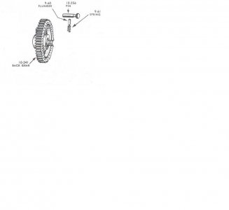
Atlas Th 54 Bull Gear Locking Pin.

Strtspdlx

Active User
Registered
Joined
Sep 13, 2014
Messages
242
The pin which locks the bullgear to the v pulley is constantly rattling loose. Given it does have some play but someone had mentioned they remembered seein a spring detent on one. So I removed the pin and found two dimples were I'd assume a spring and ball would seat to lock the pin into position. However I do not have my machine far enough apart to tell if there's an orifice for a spring and ball in the bull gear. Is my assumption correct in that I should have a ball and spring locking the pin?


Regards-Carlo
 
Yes. If you look carefully, you should find either a tapped hole or a set screw in a tapped hole that aligns directly with the direct drive pin hole in the bull gear. The ball and spring are each 1/8" in diameter and the screw should be a #10-32 cup point. I don't, unfortunately, have the spring length.
 
Gentlemen;

I just had my spindle out and took the bull gear off to examine the pin that locks it to the pulley. I could not get the pin to come out and disengage the pulley as described here and in the literature. What I found was a replacement pin by the P.O. which had a partially bored hole in it to accept a hand made 'plunger' driven by a spring. The plunger & spring reside in a hole drilled in the bull gear, below and normal to the C/L of the pin and its action back and forth. The only way I could get the pin to release (once reassembled) is to run a narrow wire down from a pre-made 'gap' in the bull gear edge at the exact location of the plunger. This wire would go thru a tiny hole concentric with the plunger and push it down while I pulled the pin back. The danger in using this set-up in back-gear mode was that there wasn't a second detent or hole to fix the pin out-of-position, only the friction of the un-seated plunger. So I opted to get a real pin, and plunger with the two detents for safe operation.

Robert, I'm not sure I understand your response about the ball; you may have mistaken it for the plunger, which is a short piece of 1/8" round stock, with a flat end for the spring, and a rounded end to engage the detents in the fixing pin.

Lou O.
 
Every picture tells a story:

The diagram labels this as the back gear, whatever you want to call it, pictured is the large gear that is on the Spindle. The step-pulley is to the left of this gear. Not pictured is the set screw that retains the spring and plunger. The original factory installed pin has no detents, rather a long flat that the plunger sits against. Spring pressure, ergo pressure from the plunger exerted on the pin, is adjusted by turning the screw.


Bull_Gear_Lock_Pin.jpg
 
So I should be able to adjust or install it from the spindle bore when it's disassembled? I wish I would've paid more attention when I took it apart to clean it initially.


Regards-Carlo
 
Spiral,

You're almost correct. I guess that I was thinking of the 6" which is as I described (set screw, spring, ball and direct drive pin with two circumferential grooves and apparently a low land between the grooves). In the 10" and 12", the hole that the ball nose pin sits in is drilled from the outside (like the hole for the index pin spring and ball) but not all the way through to the hole through the gear for the spindle. With the gear off the spindle and on the bench, you would drop the spring in the hole followed by the pin with ball-end last. Then stick something like a cutaway rod into the hole to push the ball nose pin down past the bottom of the hole for the lock pin. Finally, with the flat turned toward the spring and pin, you would stick the lock pin in the hole until it hit the installer pin, pull the installer out, and push the lock pin on in until the ball nose pin popped up against the flat. I've never taken mine apart as I've never had the spindle out of the headstock. But I assume that to get the lock pin out, you would rotate it 180 deg. to compress the spring, and then pull it out with a rag over the hole to catch the ball nose pin.
 
I'm glad I've just seen this thread as I've asked about the same situation elsewhere in the section..

Here is what I've done so far after finding that the locating pin could slip & slide as it pleased without much or any effort on by behalf.

Putting the ball bearing back on top of the spring was solved easily by using the plastic refill off a Biro , some white grease and a bent to right angle for 1/2 " piece of 1/8 dia wire with a ground or filed up right angle faced end ( don't use pliers to cut the wire ) to keep the ball bearing under compression down its guide hole , it was also long enough to make a handle to hold the wire with at the other end .

The hole was cleaned and flushed with WD 40 and blown dry using some thin tube ( borrowed off a large 1 pint WD 40 can spray head & an electrical contact spray can cleaner ) that went down the hole , I also used or use a long thin screw driver , match sticks & cotton buds to loosen & soak up the diluted crud .

Initially there was a seized in pin down the hole flat end uppermost .. a week or so of giving the hole a shot of WD40 and using a bit of rubber sleeving that just fitted down the hole over the pin to try and compress the spring & / or rotate the pin, eventually this exercise saw the pin come free along with part of a spring.
I discovered that the hole for the plunger is an eighth of an inch clearance hole , luckily I had an 1/8 " ball bearing in my bits & bobs drawers .

I use a retractable ball pen spring , cut to 3 mm longer than the hole is deep to replace the broken spring , putting the cut end down the hole first so I had a nice level platform to locate the ball bearing on once the hole was proved to be clear ( I removed the pin & bit of broken spring using a strong magnet on the side of a long thin screwdriver that I put down the hole ) .

Slid the new spring down a very thin screw driver so I knew it was in the hole right from the start . Then I used a bit of white grease to stick the ball bearing on the open end of the pen refill and slide it down the hole . Pushed it down to compress the spring , once it was below the porthole I used the bent wire to hold it down whilst I inserted the locking pin . As soon as the locking pin touches the wire press it a bit faster & harder so it travels over the ball bearing without it raising up then push bit fully home .
 
Last edited:
It was six years ago I had that apart. I stand corrected, there is no set screw and the installation procedure Robert described is correct.
 
David,

Your modification should probably work OK but a ball nose pin would be better. With no circumferential grooves for the ball to seat in (a la the 6"), the pin would supply somewhat more friction for the same compressed spring length as it can't roll like the ball sitting on top of the spring can.
 
Greetings to All;
Does anyone have a sketch or drawing of the pin (10-256) that locks the bull gear to the step pulley? I'd like to try and make one; thanks in advance.
Lou O.
 
Back
Top