- Joined
- Nov 17, 2017
- Messages
- 56
Blue,
That printed gear looks great! You're well on the way")
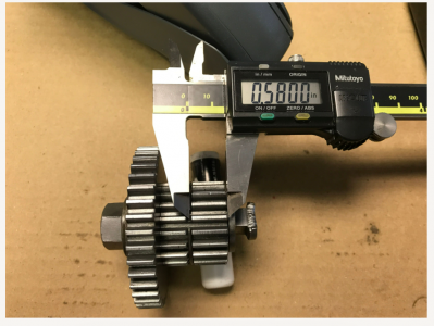
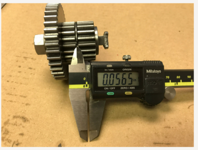
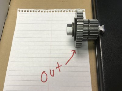
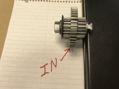
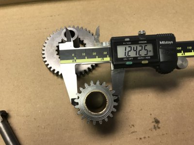
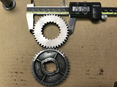
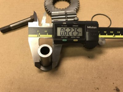
Regarding the sliding gears. The small gear (10-1243A) is 20 tooth. The large sliding gear (10-1242) is 40 tooth and the same profile as a 40 tooth change gear. And this sliding gear has the female 20 tooth gear profile on the inside to mate with the gear (10-1243A) You will notice the gear (10-1243A) has a small groove for a snap ring. The snap ring/groove really isn’t necessary if you want to leave it out of the print. It is designed so you can't move the sliding gear “IN” too far. If you did, it wouldn’t hurt anything, only change the gearing.
Important Note:
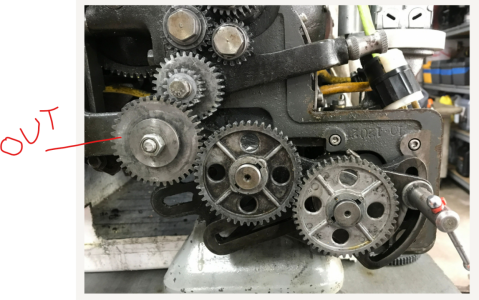
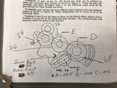
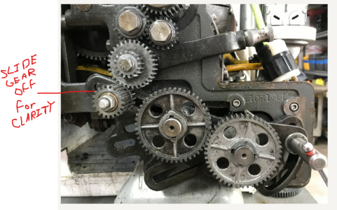
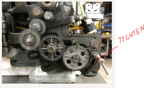
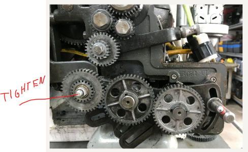
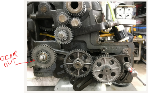
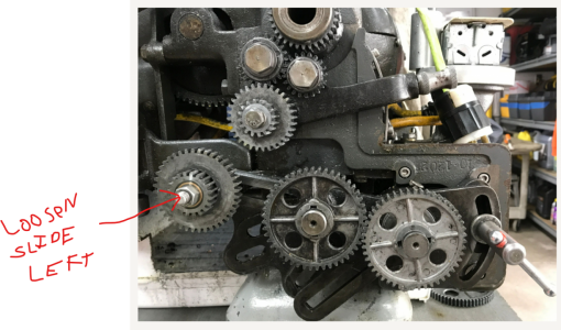
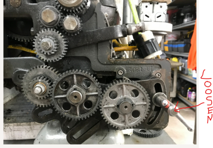
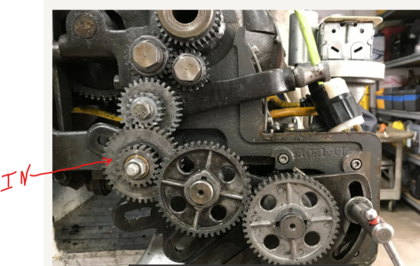
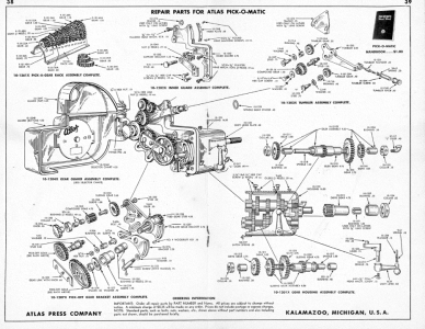
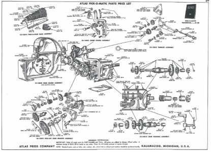
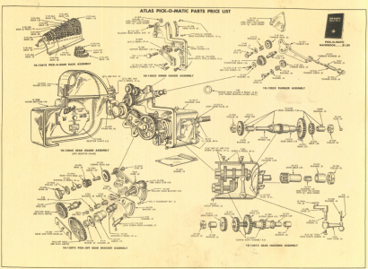
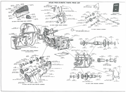
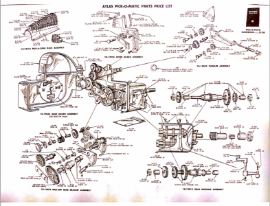
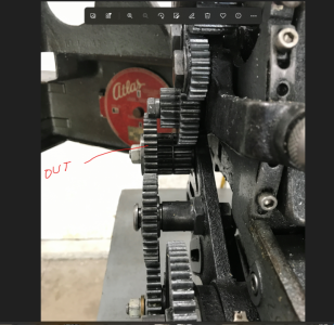
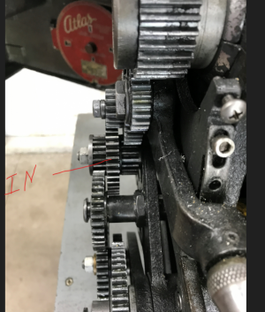
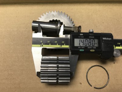
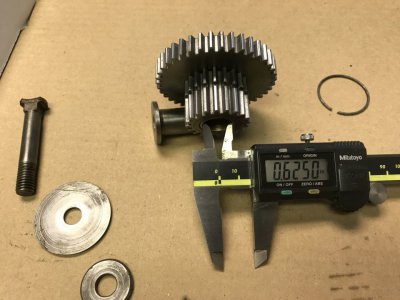
The official exploded diagram (see image) has an error in assembly. Gear (10-1242) should be to the left side of the snap ring on gear (10-1243A). When I first put mine together (following the diagram) I struggled mightily with threading. After looking at actual photographs in the Pick-O-Matic manual the error was obvious. I've attached two photos on my lathe that depict the correct orientation of “IN & OUT”. You will also notice in those images I left off the Gear Link with Knob (10-1232) for clarity. Plus, I added a couple more pictures with just the gears in the same orientation. My gear (10-1243A) is very worn in the IN position!
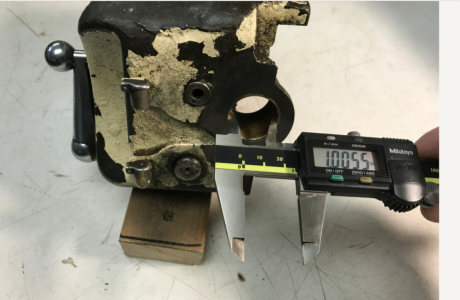
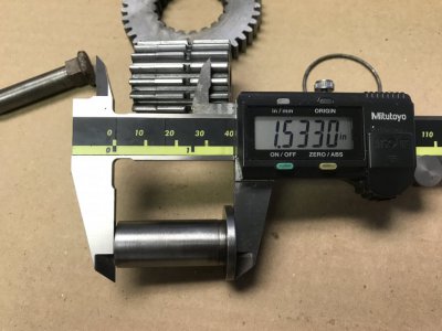
The handwheel knob is designed so you don’t need a wrench to tighten down the complete gear set. That’s how Atlas could claim you can change into many different speeds/TPI without tools. I just use a regular 3/8” nut on my gear drive as it gives me more confidence the gear set is tight. The through bolt/stud (10-1230A) can be a standard 3/8” carriage bolt with half the head ground off if you don’t have the factory bolt/stud.
Another interesting note:
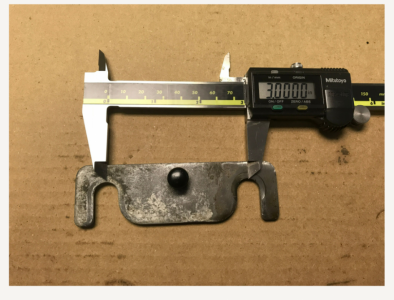
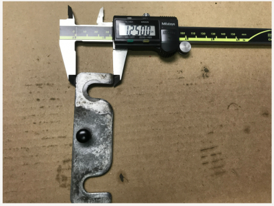
Your depicted tumbler set has a tin gear guard on the lower gear. This needs to be removed before the small Pick-O-Matic gear (10-1243A) will be able to engage in the OUT position. I think these tin gear guards were standard on gear change models, but I'm not sure about that. Nonetheless, that Pick-O-Matic gearbox probably was never operational, at least correctly, on your machine.
This is a lot of info and I'm sure I've overlooked a bunch. As you move forward, we'll iron out any issues that arise.
All the best!
Mike
That printed gear looks great! You're well on the way
Regarding the sliding gears. The small gear (10-1243A) is 20 tooth. The large sliding gear (10-1242) is 40 tooth and the same profile as a 40 tooth change gear. And this sliding gear has the female 20 tooth gear profile on the inside to mate with the gear (10-1243A) You will notice the gear (10-1243A) has a small groove for a snap ring. The snap ring/groove really isn’t necessary if you want to leave it out of the print. It is designed so you can't move the sliding gear “IN” too far. If you did, it wouldn’t hurt anything, only change the gearing.
Important Note:
The official exploded diagram (see image) has an error in assembly. Gear (10-1242) should be to the left side of the snap ring on gear (10-1243A). When I first put mine together (following the diagram) I struggled mightily with threading. After looking at actual photographs in the Pick-O-Matic manual the error was obvious. I've attached two photos on my lathe that depict the correct orientation of “IN & OUT”. You will also notice in those images I left off the Gear Link with Knob (10-1232) for clarity. Plus, I added a couple more pictures with just the gears in the same orientation. My gear (10-1243A) is very worn in the IN position!
The handwheel knob is designed so you don’t need a wrench to tighten down the complete gear set. That’s how Atlas could claim you can change into many different speeds/TPI without tools.
I just use a regular 3/8” nut on my gear drive as it gives me more confidence the gear set is tight. The through bolt/stud (10-1230A) can be a standard 3/8” carriage bolt with half the head ground off if you don’t have the factory bolt/stud.Another interesting note:
Your depicted tumbler set has a tin gear guard on the lower gear. This needs to be removed before the small Pick-O-Matic gear (10-1243A) will be able to engage in the OUT position. I think these tin gear guards were standard on gear change models, but I'm not sure about that. Nonetheless, that Pick-O-Matic gearbox probably was never operational, at least correctly, on your machine.
This is a lot of info and I'm sure I've overlooked a bunch. As you move forward, we'll iron out any issues that arise.
All the best!
Mike
Attachments
-
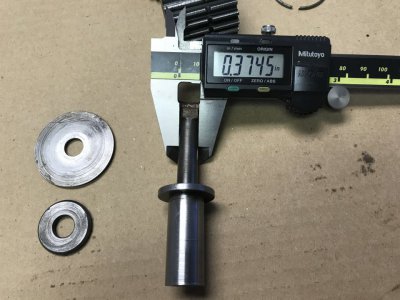 10-1230A Diameter .JPG132.2 KB · Views: 15
 -
 Sliding Gear OUT .JPG91.2 KB · Views: 12
 -
 Sliding Gear IN .JPG95.5 KB · Views: 10
 -
 My Lathe Sliding Gear OUT .png646.7 KB · Views: 11
 -
 My Lathe Sliding Gear IN .png615.6 KB · Views: 12
 -
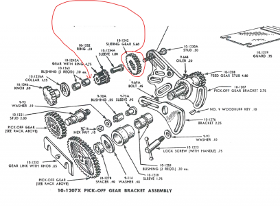 Exploded Diagram with Gear Correction .png361.4 KB · Views: 13
 -
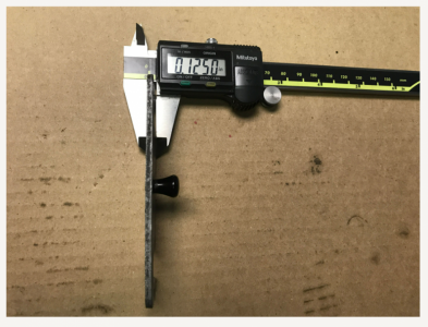
 10-1243A Overall Length .JPG113.2 KB · Views: 10
 -
 10-1243A Inner Diameter .JPG114 KB · Views: 10
 -
 10-1243A Groove Diameter .JPG107.2 KB · Views: 9
 -
 10-1242 Diameter .JPG141.1 KB · Views: 9
 -
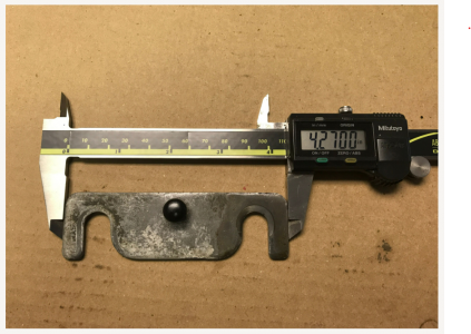
 10-1234 Overall Length .JPG104.2 KB · Views: 11
 -
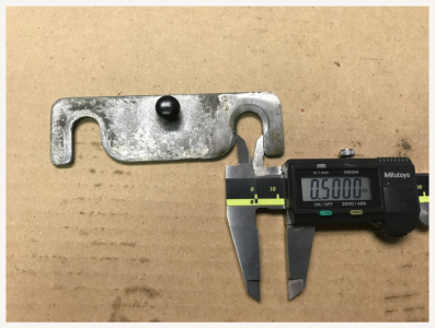
 10-1234 Diameter .JPG104.7 KB · Views: 14
Last edited: