Are most rotary tables like this?

well, then we need to see what was going on in the 30s to the 70s here in the USA.. were they all as you think, or did they vary? I'm not sure.
Maybe we can ask some guys out there with some old equip what it looks like.
Not sure if the old iron was made "well" or not. Not relevant for my needs. RJ's table seems to be fine. Mine isn't.
PXL_20220227_154048457.jpg
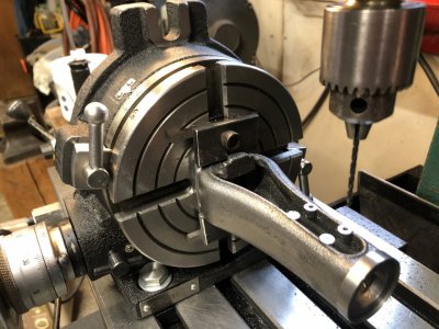
For me, the scale reads 3 degrees and 11 minutes, if I am getting this right. The horizontal slots are aligned with the x axis of the mill table. So shifting the pointer isn't really going to help. Crudely, it is fine. I can make a pointer to zero. But to get things precise, I have to set to x + 11 minutes to get everything to come out right. It may not matter to you, but I don't like that error. A 3 degree error is ok, but not convenient. 3 degrees + 11 minutes, no, that's no good, as it will lead to many screw ups in setting. A multiple of 4 degree error would be fine, as the dial would read correctly.

I am going to watch some rotary table teardown videos to see if I can understand this RT some more. Maybe it is adjustable, maybe not. Hope to learn some more about the table. The exploded part diagram I have is a print of a xerox of a xerox, if you catch my meaning. The detail is blurred, so I don't quite understand it. Once I understand it, I can tear it down, if I need to.
 
I took a closer look at my 6" RT and the offset is actually about 20º. The design of the base fairly well precludes aligning the index mark with one of the four cardinal points. The RT is a H/V model and placing the index on the surface next to the vertical base would make it virtually impossible to see when used in the vertical position. The opposing surface and back surface would be inconvenient to see as well. That leaves the front surface and the 20º offset.

The Tormach RT is a 4th axis RT and I can arbitrarily set the zero degree mark wherever on the DRO readout so not a problem but the Phase II manual version this is built on has the same offset.
 
My Enco RT has an adjustable dial so I can set the the fine adjust to anything within a 4º range. I use the index marker and degree scale for a rough setting only and make my fine adjust with the dial. The 90:1 worm gearing ensures that I drop into the same relationship between the dial and the table whenever I disengage and re-engage the worm drive. @WobblyHand, if yours is configured similarly, free rotating to a new position and remembering to add/subtract a 3º offset should get you where you want to go.

When working with the RT for a complex set of rotations, I always make up a table of positions for each operation. It saves the wear and tear on the old noggin and potential head injuries from banging my head against the wall when I screw up a part.
 
Stefan Gotteswinter to the rescue. Saw his teardown of his Vertex HV-6.

Have a much better feeling for how the table works. I'll try taking out that 11 minute offset. If successful, I will try to take out the 3 degrees + 11 minutes. I'll try this right after lunch. For all I know, this is trivial - or it opens a new can of worms, will find out soon!
 
You guys are blinding me with science.
in the old days when I did this for a living I only used the RT’s (great huge ones) for making wheel centers for & also hubs for axles. And bolting fixtures to RT’s to machine other parts with round nose end mills, etc, etc.
never used seconds, etc.
I’m not an expert.
The silver line on the RT body next to the rivited-on pointer is how I used to zero everything out.
Disregard the set-up, this from couple years ago, only meant to show the verithin pencil mark.
iI always thought my 6” table was a re-badged Vertex, I now think it is a re-badged Vevor.
And the large Yuasa & Troyka etc. RT’s i used for a living were Swiss Watch’s compared to my little 6”one.
But it works fine for me in my little garage machine shop with my little machines, now that I am retired
Cheers :)
 

Attachments

  • EB8F23B6-36AF-447C-8CF5-0020215F684A.jpeg
    EB8F23B6-36AF-447C-8CF5-0020215F684A.jpeg
    148.3 KB · Views: 24
not sure I understand. I didn't see anything in that video about what you are talking about.
 
not sure I understand. I didn't see anything in that video about what you are talking about.
He didn't even mention offset. Of course, it may have been trivial for him to deal with. Stefan does stuff in a matter of fact way and often assumes we all know some (basic?) things. I just needed to see the same model RT come apart, to better understand how it worked.

Honestly, I just want to get rid of the 11 minute offset as that will mess me up. If the level of minutia gets too great (pun actually intended) then I can get overload and forget things. Personal frailty, I suppose. Keeping things to degrees is my way of dealing with it.
 
Does the pointer adjust side to side if you loosen the screws holding it?

If it doesn't move far enough, I would use a Dremel to slot the holes enough to adjust out the 11 degrees...

If might be more simpler to set the rotary table at the 3 degree mark exactly, lock the table, then loosen the mounting bolts and indicate the t-slots by moving the entire unit... like you would a vise.

Unless, of course, the rotary table is 'keyed' to the mill table... I always just remove the keys, anyway.

-Bear
Yes it does adjust some, but not enough. So I could slot out the hole some, or make a new pointer. Only thing that bothers me is the 11 minute offset. That is the part I need to take out, at least to make the fixture plate (unaltered).

I agree, but it would make this a pain in the behind to set up. But this really is a one shot event (I hope). Might be ok.

I haven't keyed the table. Personally, I don't like having the tooling sitting cockeyed on the shelf. Haven't ever found it a problem to tram dividing heads, vises, or rotary tables. Only takes a couple of minutes. Just have one partially tightened bolt as a pivot, and the other one looser. Indicate, tap, repeat a couple times and you are done. Then tighten carefully. Pretty quick in practice.
 
You guys are blinding me with science.
in the old days when I did this for a living I only used the RT’s (great huge ones) for making wheel centers for & also hubs for axles. And bolting fixtures to RT’s to machine other parts with round nose end mills, etc, etc.
never used seconds, etc.
I’m not an expert.
The silver line on the RT body next to the rivited-on pointer is how I used to zero everything out.
Disregard the set-up, this from couple years ago, only meant to show the verithin pencil mark.
iI always thought my 6” table was a re-badged Vertex, I now think it is a re-badged Vevor.
And the large Yuasa & Troyka etc. RT’s i used for a living were Swiss Watch’s compared to my little 6”one.
But it works fine for me in my little garage machine shop with my little machines, now that I am retired
Cheers :)
It appears your 0 on the dial lines up with the seconds 0, when your slots are vertical. Mine doesn't do that. How did you make that happen? Loosen the table and turn it? If I were zeroed like that and the pointer was off, I'd just make an offset pointer, like you did. (The line.)

Right now I have locked my table in the right position, (both the RT and it's horizontal slots are trammed) but not sure how to get the dial to zero without a lot of trial and error. I'll mess with it some...
 
Back
Top