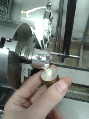
Apprentice exercises.

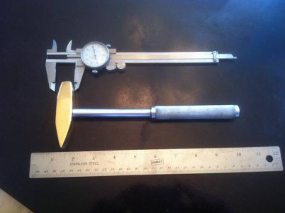
Okay, I've just been doing some work on the above hammer.

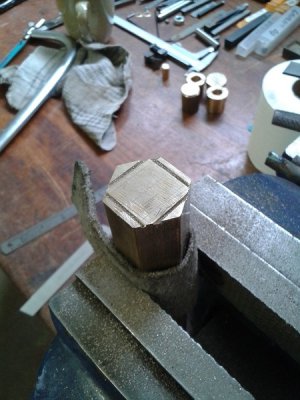
Firstly I didn't have any square stock in brass, so I set about taking a piece of hex stock to size. The offcuts will be saved for the furnace.
20140109_130348_zpsa09602de.jpg

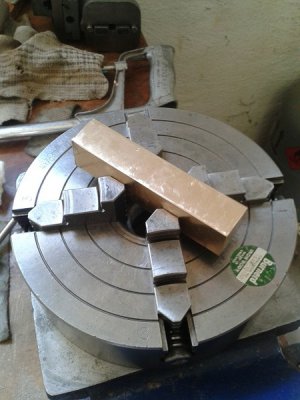
After I had cut it to rough dimensions I started filing the surfaces, a second cut pillar file worked well. Although I found it relatively easy to flatten the surface down the long way of the workpiece I had great difficulty getting it flat across the short way. I can only get it slightly rounded, not actually flat. Here's the workpiece in a four jaw chuck, about to be put on the lathe.
20140114_143551_zps4c57fa7d.jpg

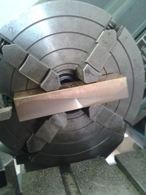
After starting to turn it seems I was quite off on some of the surfaces, the one pictured here being the most out.
20140114_145146_zps7d1004d0.jpg

I squared it up nicely, should be able to do some more work on it soon.
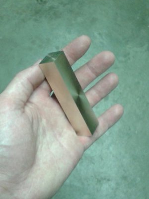
20140114_210305-1_zpsa9ac1c7c.jpg


I am going to have to wait to get the Southbend workshop projects book, I have someone coming over from the UK soon who is going to bring my books over but unfortunately I just missed a copy of the Southbend book! Oh well, next time. I've also picked up some stainless square stock for making dial indicator clamps, I still need a few more materials for those though.

Carlos.
 
Since there was some interest...

The brass head of the hammer started life as a 3.5" piece of square .750" brass stock. The sharp tapers to the tail start 1.250" from the back and taper down to a .100" trailing edge. The more subtle taper to the head, start 1" back from the face. I remember my teacher critiquing that head tapers were cut incorrectly. Only the corners were supposed to be tapered. The layout lines on the original prints were trying to illustrate a chamfer to run on the 4 corners .150 deep at the face. I cut off too much material. The blue print (mimeo-graphed, as photo copiers had yet to be invented) intended to have the sides un-taperd to the face, giving the hammer more head weight than it has. Not a problem. it's almost perfectly balanced. Since it will never be used to hit anything anyhow, the extra bevels give more surfaces to reflect light.

The center hole for the handle is 1.625 aft of the face. The .325 hole was under drilled and tapped to receive the threaded 3/4" end of the handle. Sorry...can no longer remember the thread pitch, except that it was coarse and the blue prints were never saved by me. It's locktighted on and severely torqued in place. I remember clamping the handle in a wood jaw vice and using a 2' steel channel to torque the head on until the threads married. Not sure if there is much galvanic activity between aluminum and brass, but it's now on there forever.

The 9" aluminum bar-stock handle is turned to .680 for 4.5 inches, then knurled. A .200" bit is left un-knurled at both ends. The remainder of the handle is turned and highly polished to a final dimension of .465. All of the final finish was done by hand using files, then progressively finer emery cloth and ultimately hard hand polishing on a terry cloth towel, stretched taught on a flat piece of lumber, with rubbing compounds and finally "Brasso" brand metal polish as a mild abrasive.

As an adult I now own the tools to make this project much easier than it was in H.S. shop class.

photo_zps9ccdd6c5.jpg
Thank You so much,
I love the look of that hammer! I am so inspired, i want to try my best to make one.
I wanted to personally thank you for taking the time to type out this thread.
Simcerely,
Jon
 
Last edited by a moderator:
Okay, I've done a little more work with this.

I decided I'll use a fly-cutter to machine the flats on the hammer. So I set about making a fly-cutter.


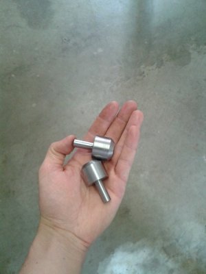
The blanks I made are intended to be threaded on the shank so I can fix them to the faceplate. One of the blanks is not drilled as it is intended to be a counter weight. Seen below are the blanks.

20140121_093729_zpse9d471e4.jpg

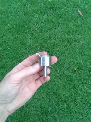
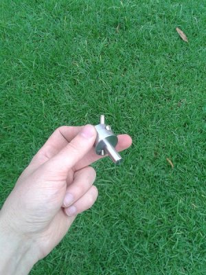
The finished fly-cutter.

20140121_171621_zps7ccb21a9.jpg

20140121_171613_zps5939daa6.jpg

And a test on some scrap brass.

20140121_173014_zps6c69e5b1.jpg


Now I need to draw up my hammer design and get machining. I've attached drawings of the fly-cutter for those interested.

Regards,
Carlos.
 

Attachments

  • flycutter1.pdf
    182.6 KB · Views: 23
The duplicate counterweight is a good idea! Nice job!
 
Almost 50 yrs ago when I was a 15 yr old boy apprentice electro mechanical engineer in an engineering college , lathe work was the second years level of our apprentice ship . Mathematics , geometromy and trignometry were pounded in to our skulls every day for the first year along with electricity & magnetism , heat and light , workshop processes & materials .

Most of the first years hands on stuff was spent file pushing and learning how not to break hacksaw blades , how to use almost any sort of hand tool or workshop machinery safely & effectively , how to sharpen twist drills and some basic blacksmithing .

The blacksmithing period resulted in a set of punches and cold steel chisels comprising of a 4 " centre punch , a 4 " x 1/8 " round nose punch plus a 6"x 1/4 & a 9" long 1/2 " round nose, The chisels were a 9 inch long diamond point , a 6 " x1/2" & a 9 " x 3/4 inch cold chisel all in high carbon steel which had to be correctly hardened and tempered using a bright red hot cast iron block out of the forge as the heat source for the hardening & tempering .

The lathe work started out as making a set of four parallel pin punches and knurling the upper ends plus hardnening & tempering . Then to fit in with some of the file pushing exercises we'd done in the first year we turned screw threads , knurled the ends for finger grips and made a simple " F " type hand held vice .

Some where around here I made a set of 3 & 6" calipers , a pair of dividers and an hermophrodite ( odd leg or jenny ) calliper and a case hardned scribing block for use on the marking table ( I use a 24 inch square sheet of 12 mm plate sheet float glass for my marking table these days ) .

Sheet metal work started to show it's ugly head.
I made a 18 x 12 x 12 steel tool box with wired edges & an internal small tool tray . Working out radi and spacing for precision blind aircraft rivets round a hole I had to cut and hand finish in a curved Duralumin surface off a scrapped helicopter was very exacting and interesting as it was clamped vertical onto a post just for a buggerance factor and developing my skills..

Machining started to appear around now and one of the exercises that really took my fancy was a lathe turned one inch cube out of a 1 & 1/2 " block that had to fit into a precision ground and milled 3 x 3 x 3 inch thick block of mild steel turned down to one inch thick plate with a centrally located one inch square clearance hole through the middle . Your 1" cube had to pass through at all faces and not have more than 1.5 thou of an inch clearance . It also had to be polished to a mirror finish.


I'm a recent new member to the site who has finally managed to get hold of a mint condition ancient 1943 British made ( Atlas style of1942/3 or so ) Sphere 10 inch lathe.

I rewired it up with a safer emergency stop/ start button set to the right hand of the front side so that I'm always going to be well out of danger of things flying off the lathe when I start it up after changing the gearing or inserting a work piece etc.

I've got to start making a few things before I get my sleeves rolled up and start turning up some 40 or so pieces of aluminium bar .

Tonight I ordered 56 pounds of sensible sized bright steel off cuts from someone on eBay along with the aluminium bar and a 100 mm x 100 mm x 10 mm thick lump of flat bright steel bar which I will have to cut to 80 mm square and drill a 15 mm cente hole as it will become the packing base / washer for my new to me quick change tool post .

I have to make a new tool post holding " T " bolt or make a correctly sized " T " nut to fit the cross slide tool post mounting grove.

All this preamble done I'll be running off the turned aluminium and then horror of horrors attempt to make a new cross slide handle in bright steel with a mounting keyway as the current one is missing one of the legs / arms .
If anyone has ever turned a mono block one on a bog standard lathe would you be so kind & post general destructions of how you did it please?
 
Last edited:
hello, my apprenticeship training consisted of a 5 hole hole pattern with the only spec given was 2 " on center 1/4" hole plus on minus .002" each hole was inspected by the instructor. this taught you how to figure out triangles, move a mill and account for all slop in the mill on a mill with a tag on it that stated that the machine was finished in a hurry to meet wartime production needs. worn out years before. no dial indicators were allowed. and a major threading project which consisted of a single lead ,a double lead left handed. a 3 lead right handed and a 4 lead left handed acme with nuts to fit all threads measured with a 1 or 3 wire method. a taper sleeve and lots of work around the shop in many sections. mills, lathes, grinders, turret lathes cnc machining tool and cutter grinding tool and die maker section large machines , pump and valve rebuild carbide room and tool crib all this tool 4 years, It was a great apprenticeship and thanks to our government havinglots of time and money I learned a lot some easy some the hard way. bill
 
I have various prints for an Apprentice (or newbe) that will require a Lathe, Mill, Surface Grinder and a torch (Oxy/Acetylene with a "rosebud" tip) and air compressor (for heat treat)...and a good, precision angle plate and a V block (s) (borrow?) to get started on making an angle plate 1st...They (the prints) are to make V blocks, angle plates, 123 blocks, parallels, precision vices, sine bars...a universal block (to accept 5c collets) + hammers (nylon or delrin etc. on one side, brass on the other)...+ some other "stuff"... ifn' I can figure out how to copy and post them (the prints) here I will do so...all will need to be made out of a good tool steel such as D2 (my favorite air hardening tool steel to HT to rc58 to 60) and some "prehard" (maxel 3 1/2 (brand name) is my favorite (around rc30)...everybody during my 5 yr apprenticeship was able to make these during our 1st yr or so on our own time (but in those days Mgt looked the other way so we made them on Co. time!! (This proved to help make a better (skilled) employee for them)....once these items are done and made with pride yoose' are about half the way "there" (actually, after over 35 yrs of chewing metal I am and always will be only half the way there!) ...Cheers!!
 
A few years ago I designed a clock to be made by inexperienced amateurs on a small lathe.
quite a few are being built around the world with good results.
Have a look at my web site below or look at http://www.hobby-machinist.com/threads/a-beginners-clock.9737 and see if this fits your needs . a full backup service is provided.
This is not an advertisement, just trying to point out other ways of learning.
Brian
 
Last edited by a moderator:
Unfortunately Brian that link doesn't seem to work. I think one of the upgrades between then and now might have lost it

cheers Phil
 
Back
Top