Another Furnas switch question

I do have multi meters.
In the “off” position, all contacts of the switch rotor are in between all the the fixed contacts. I’ve checked continuity on the switch in Fwd and Rev, and the contacts make up like the fuzzy drawing shows.

The links are installed according to the motor plate for 115v.

I think the blue wire replaced one of the factory black wires at some point.
The black wire with the splice perhaps was extended from the capacitor to take it all the way to the switch.

Running it without the reverse switch is a good idea. I’ll see about trying that out this evening.
 
Last edited:
OK sounds good- Looking at the photo of this motor you may need to purchase a different reversing switch; the motor's internal centrifugal start switch is sometimes internally connected to (and is physically part of) one of the main terminals. With some hookups the start winding doesn't shut off and the motor will overheat.
Get it running by itself first and we can go from there.
-Mark
 
Last edited:
So far, a lot of "foo fah rah" that hasn't told you much. Let's back up a little and start from scratch. First off, never mind the switch, just consider the motor. A single phase motor will have two windings, the RUN and the START. In a dual voltage motor, the RUN winding may be in two parts. In that case, choose whether you want to run 120 or 240 volts. The RUN windings will be paralleled for 120 volts, seriesed for 240. The START winding usually is 120 volts only. If 120 volts it will be connected at one end, if 240 it will be connected in the middle, at the common termination of the two RUN sections.

The motor can be run on the bench without the START winding connected. The motor must be started by rotating the shaft in the desired direction. And done so within a couple of seconds, quickly so the magic smoke doesn't get out. This is handy for determining which end of the RUN winding section is which. Tests are done on 120 volts, of course. Even if the motor is to be run on 240, it can be tested on 120, so long as it isn't connected to a load.

Now to look at the START winding. This will consist of the START winding proper, a capacitor, and a centrifugal switch, all in series. The complete circuit will connect to the RUN winding on one end (or in the middle for 240) and the line on the other. Direction of rotation is determined here, by swapping (reversing) these two leads. It doesn't matter which item is where in the series circuit, just that all three are there.

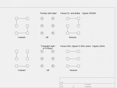
Now we can go into the switch. I will illustrate a switch that I have used on several machines. It is NOT like the Furnas but will illustrate the concepts I need to convey. The switch will actually consist of three sets of contacts. This is where the VOM (Ohm Meter) will pay for itself. Or simply a buzzer and battery will suffice. Any sort of continuity tester. . .

With the switch centered, there should be no connection anywhere, a given. When the switch is thrown in either direction, there is one set of contacts that will make up the same in both directions. That is the line switch, between the line and the motor.
1663818093054.png
In the photo above it is the top of the three. It will be different on the Furnas, as well as Sq D and many other switches. That leaves the other two switches as a "reversing" pair. On the illustrated switch, the START winding will connect to one side of the switch, the other side connecting to the motor. Where and how the connections are made will be different for most drum switches. But the function will be the same for all. The premise will be to reverse the relationship of the START winding to the RUN winding, reversing the motor direction of rotation.

It must be remembered that for single phase motors, reversing can only take place when the motor is at or near zero speed. Slow enough to close the centrifugal switch. Unlike a three phase motor, where the "T" leads can be swapped at any speed, reversing the motor. But many (most?) of us are "casual" users and don't have three phase power available.

EDIT:
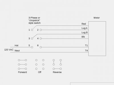
According to the nameplate above, there will be six (6) leads available. Two each for RUN winding sections, and two for the START sequence, a total of six(6). It will be up to you to determine which pair is which since the colors have been changed. Any two will be a pair, two pairs a winding, probably a RUN section. One pair will give an anomolous reading, depending on what type of meter is used to check continuity. That will be the START pair, I use a Simpson 260 and/or a Fluke 76. One an analog and one a digital, giving decidedly different reactions to a capacitor. Whatever reaction is given to the capacitor, that is the START pair. Once you have determined each pair, each winding, just follow the nameplate diagram. Changing colors where applicable. . .

.
 
Last edited:
Thank you for the breakdown. That was helpful! I’m much more familiar with three phase, medium voltage stuff, and typically have an elementary to work off of. These dinky little old motors make me think too hard… But your explanation helped and got me to thinking, but less painfully.
Something just wasn’t making sense with this motor, so I removed it from the lathe and took the end bell off.

I was able to determine the run windings and start winding.
Here is what I found, from looking at the little phenolic board where everything makes up inside the motor:
CA5A2651-E704-41B7-B110-48C32995E7DB.jpeg

Both A, T1, and 1 are connected to the thermal switch, and 2 is connected to 1 via the removable link.

B goes through the centrifugal switch and connects to 3, which connects to 4 via link, which is connected to T4.

Basically everything on the left side is interconnected, and everything on the right is interconnected. This is without any motor leads connected (well, one run lead is soldered to the thermal switch, but the rest connect to tabs on the board).

I thought- if everything is interconnected, I can just run two wires to the fwd/rev switch and flip them between hot and neutral. The only thing in the circuit that really affects anything is the capacitor, right? Apparently not… here’s how I connected everything, including my diagram of the factory interconnection of the board in the motor.
C16A1700-2E32-4EAD-B371-1A0EB45F7BE2.jpeg

The motor runs fine! However, it runs in the same direction, whether in fwd or rev. I thought about extending the wires from the start winding to the switch, but that would bypass the thermal switch and centrifugal switch, since they are interconnected on the board itself.

What am I missing this time?

Thanks!
Nooj
 
Watch that "thermal" switch. If it can be isolated, it should be in the RUN winding where it is completely separate from the START circuit. Also, very important, is that it must not be an "automatic reset", it must require a manual operation. To have the machine start when you are looking for a problem is dangerous at best, deadly at worst. Such a device is often completely disabled on many "hobby" level machines. Keep in mind that blood is highly corrosive on iron and will damage the machine if it touches it.

Somewhere on the reversing switch is a reversing, or cross wiring, function. Most every switch has this arranged somehow. It will be separate from the RUN function. The START winding must be connected through this reversing switch. I personally run a four conductor cable indepentent of the RUN winding. It can be done with fewer wires, that's for the individual user to work out. For me to work out the contacts of your particular switch, I would need the switch in front of me, and a functional mind. The latter being rare these days. One simple solution would be to use a different switch, like the one I have pictured above. The cost is not that much and wiring is obvious.
Such would be my suggestion. The few downsides are the time required to get it and the (rigid) plastic case. When I ordered mine, I got extras above what I needed, for spare parts. Haven't needed any, yet, but I am a very casual user.

The bottom line is that there must be six(6) wires connected on the reversing switch. There must be a way to reverse the two START winding leads, which requires four(4) leads alone. Adding the RUN wiring brings the total to six(6). How these are arranged is dependent on the switch and personal taste. The latter where the incoming power lead is brought into the circuit.

.
 
I hear ya on the “functional mind”… I’ve been in a fog.
I think I know what I gotta do, pretty much what you said. I’ll do some figuring out once I get home.
 
As an aside, I will be offline a couple of days. Should be back Sun evening if needed.
 
I think the start circuit is still miswired vs the drum switch terminals- the start "leg" needs to reverse polarity with respect to the main winding(s) to reverse
I'll take a closer look in a while- back soon...
-Mark
 
I think the start circuit is still miswired vs the drum switch terminals- the start "leg" needs to reverse polarity with respect to the main winding(s) to reverse
I'll take a closer look in a while- back soon...
-Mark
Exactly what I’ve figured out.
The problem is that the little terminal board is hard wired to where you can’t swap the start circuit, because it will create a dead short between hot and neutral. I don’t believe this motor was made to be used with a reversing switch. ( you can change directions by moving where the start winding connect to the board, but can’t remote swap them with a switch).
I may be able to modify it to work, by removing a couple factory jumpers on the back of the board (some are metal straps riveted in place), and soldering in some wire to create the path I need to separate the start winding completely from the run winding, but still keep the centrifugal switch.
However, I would have to remove the thermal switch from the start winding circuit completely.
 
There are two basic styles of reversing drum switches- for this particular motor the one you have isn't ideal
Yes, you could go behind the terminal board and start hacking as you described, but with a different style drum switch
you could avoid all the painful surgery: (post #13 Bill shows an example- about 12$ on Amazon)
 

Attachments

  • Drumstyles1xe.jpeg
    Drumstyles1xe.jpeg
    62.4 KB · Views: 20
  • drsw120a2ax.jpeg
    drsw120a2ax.jpeg
    51 KB · Views: 15
Last edited:
Back
Top