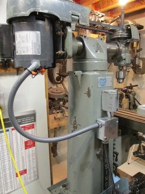
Another Clausing 8530 milling machine

that's curious, looks like the polarity of the run windings is switched between forward and reverse. You also appear to have a capacitor start motor and I don't know how they behave compared to split phase centrifugal switched motors (the only ones I've had experience with). Other than wiring it up as the wiring diagram suggests, I think I'd better bow out before I offer incorrect advice!
 
Outboardguy, you need to follow the diagram in the upper left - single phase with a split phase motor. The wiring in this case is nearly the same as the one that I had posted a while back except for some of the wire colors. The colors don't mean anything and can vary from one manufacturer to another, even model to model. The idea is to create the same wiring pattern.

The following wiring should get you the results you need:
1. Connect your 110v hot lead to terminal #2 on the switch. Connect the black lead from the motor here also.
2. Connect your neutral to terminal #6 on the switch.
3. Connect the red lead from the motor to terminal #5 on the switch. You will also need to run a jumper between #3 and #5 on the switch.
4. Connect a wire from the #1 post on the switch to the #1 post on the motor.
5. Connect a wire from the #4 post on the switch to the #4 post on the motor.

If you run the motor it should now run in both directions, but make sure that you allow the motor to stop before starting it in the opposite direction. Split phase motors have a centrifugal switch that disconnects the start windings once the motor is running. If you have the motor running and suddenly flip the switch to run the other way, it will just keep running in the same direction that it had been.

If you find that the motor is not running the direction you want it to for the direction of the switch that is selected, you can reverse it by switching the red lead to terminal #2 on the switch and the black lead to terminal #5

The key thing to remember is that motor rotation can be reversed by swapping the two run winding leads OR by swapping the two start winding leads. It really doesn't matter which.
 
Sorry Outboardguy, been working 18 hr days. Finally got a day off.

Terry is correct about the wiring.


So if my brain is working right this morning, you will have 2 wires coming in to your drum switch (hot and neutral) connected as Terry said to termials 2 & 6 respectively on the drum switch.

You will also need to run a jumper wire between drum switch terminal #3 and drum switch terminal #5.

You will have 4 wires running from the drum switch to the motor that will connect to the spade bit type connection points on the motor as follows.

Connect wire from drum switch terminal #1 to motor connector #1.
Connect wire from drum switch terminal #2 to motor connector #2.
Connect wire from drum switch terminal #4 to motor connector #4.
Connect wire from drum switch terminal #5 to motor connector #5.

Motor connector should be male spade bit type connectors. From the picture they are as follows:
#1 - Top left of motor wiring picture. The male spade bit connector appears to have a black wire connected to it. This should be the wire for the starting winding shown on the drum switch wiring diagram (terminal #2 connection) and will have to be disconnected from the motor spade bit and connected it to the wire coming from drum switch terminal #2.
#2 - Should be the male spade bit connector top center of the motor wiring picture with Red and Blue wires connected to it (connect to unused spade bit in middle).
#4 - Top right of motor wiring picture.
#5 - Should be male spade bit connector bottom center of motor wiring picture with Black wire on it.

If this doesn't work, it's because the two black motor wires have been swapped (the ones connected at motor connections #1 and #5)
Like Tery said, if not running in direction drum switch shows, just swap wires #2 & #5 either at the drum switch or motor, shouldn't matter which.
 
Ok I did try this out the way Terry described, but I've managed to not get it quite right yet. The motor will run in both directions, but is noisy and is starting to overheat. Too tired to look at any more wiring tonight so I'll give it another go tomorrow. Thanks for the assistance.

Best,
Chris S
 
Post a couple pics of how it's wired now. May help with what's wrong.
 
Work has been a bit of a bugger lately so there's not been a lot of time to work on the mill. I finally did have another look at the wiring on this thing and only solidified my suspicions that the main problem is that I just don't know enough about how electric motors work. So, I called an acquaintance who does know about that sort of thing, and he dropped around and got me straightened out. Well, actually what he did was to install a new run of wire and outlet so I can run the lathe and mill on 220v instead of 110. This is what he installed on the machine. it's all good now. Thanks to y'all who tried to help, I do appreciate the advice that was offered.

Clausing Mill 014.jpg

Best,
Chris S
 
congrats! as long as it runs properly, who cares how it got that way :)
 
Back
Top