-
Welcome back Guest! Did you know you can mentor other members here at H-M? If not, please check out our Relaunch of Hobby Machinist Mentoring Program!
You are using an out of date browser. It may not display this or other websites correctly.
You should upgrade or use an alternative browser.
You should upgrade or use an alternative browser.
Adjustable Vise Mounted Work Stop System
- Thread starter mksj
- Start date
- Joined
- Jul 19, 2019
- Messages
- 116
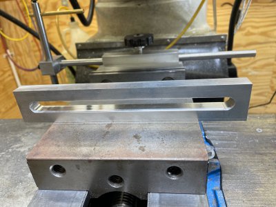
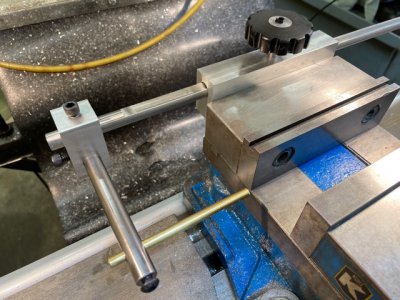
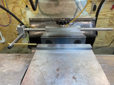
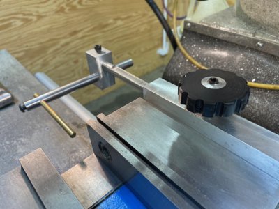
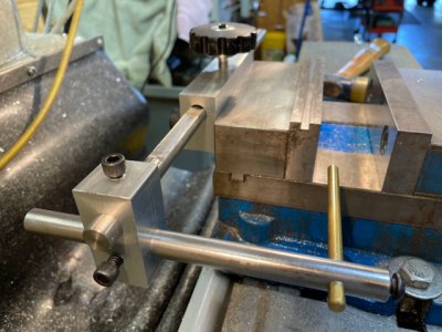
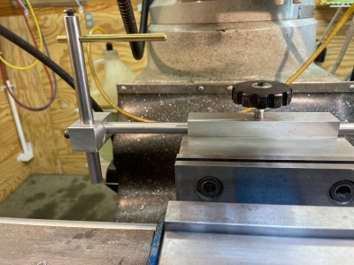
Beautiful work Mark. Very impressive as always!I have been using a T-Nut type vise stop system, kind of flops around, was hard to adjust, and just tired of cleaning all the swarf out of the T slots. I wanted to come up with a stop system design that mounted to the back of the vise so I can install covers over the mill bed, was easy to adjust in any one axis and had a wide adjustment range. The design I came up with mounts a 5/8" round bar to the back of the vise, and also adds a taller 1" thick jaw that I can use to hold bigger work on the vise. There is a single adjustment lever at the front and back of a sliding T-Nut adjustment system, and each one can lock two axis at the same time. The adjustment stop system was milled from 6061, adjustment bars (3/8, 5/8") from O1 rod and 1018 CRS used for the rear jaw stop. This stop system was more of a different design setup as opposed difficulty in machining the parts. One challenge was drilling the 5/8" hole through 6" of 1018 CRS, I drilled this from both sides so required accurate alignment, would have been nice to have a 5/8" reamer to takes clean up the hole, but just ran a long 5/8" drill back and forth through the hole. The 5/8" rod has a flat milled on the top which locks the bar in the same plane and will not be damaged by the locking lever when tightened.
The two rod clamps are sized slightly different and slide in the T with an opposing sliding T-Nut underneath. The sliding T-nut type design has split clamps and can adjust both X and Y, Y and Z, or X with a single lever. It seems to be quite rigid, gives a wide range of adjustment and can swing back or be removed quickly. Next project will be to make swarf covers for the mill bed on either side of the vise and a front taller Jaw.
View attachment 369590
View attachment 369591
View attachment 369592
View attachment 369593
View attachment 369595
-firemaker76
- Joined
- Mar 25, 2013
- Messages
- 4,643
I must ask how you drilled the long hole in the rectangular block that attaches to the vise. How did you get this aligned straight? I can think of several ways to do this on the mill or lathe. How did you do it and what do you recommend? I pose this question to anyone with an opinion!
Robert
Robert
Last edited:
- Joined
- Jun 12, 2014
- Messages
- 4,826
The 5/8" hole is 6" long in 1" CRS 1018, I drilled mine from both side, first with a 1/2" drill and then switched to a 5/8" drill. I had a longer 5/8" drill that I could run the length. My mill setup (DRO and edge finder) repeat to ~0.0004" so flipping it accurately was not much of an issue. If needed one could sweep the length with a test indicator vertically. It also depends on you squaring up the block accurately.
I always start my holes with a center drill or stubby and then switch to a longer drill for a deeper hole. Locating and drilling both direction by scribing would be challenging, one could setup a jig using a ground 90 degree angle and some blocks.
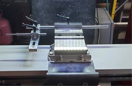
I also added a a taller jaw to the front of the vise, so it is much quicker to clamp larger pieces using the outer jaws and they have a taller profile then the stock ones.

- Joined
- Mar 25, 2013
- Messages
- 4,643
Interesting. Two ideas occur to me. I was planning on a 1/2" hole. On the mill, I could drill 15/32" from each side and then drill 1/2" all the way. I could chuck it up in a large 4 jaw on the lathe and drill the entire length. My vise is only 4" so a little easier.
I am thinking the lathe in a 4 jaw is the way to go?
Robert
I am thinking the lathe in a 4 jaw is the way to go?
Robert


