Adjustable Vise Mounted Work Stop System

mksj

Active User
H-M Lifetime Diamond Member
Joined
Jun 12, 2014
Messages
4,833
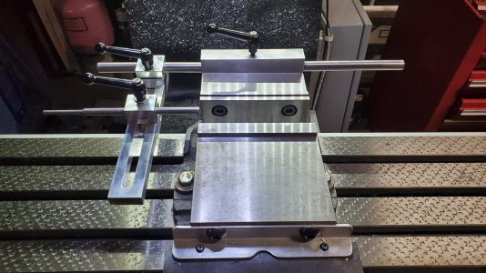
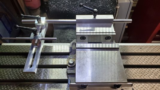
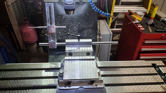
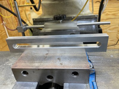
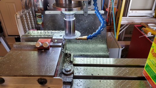
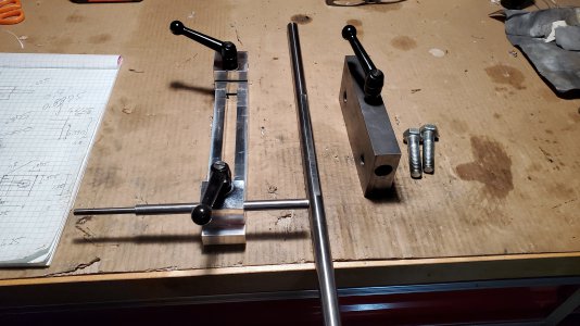
I have been using a T-Nut type vise stop system, kind of flops around, was hard to adjust, and just tired of cleaning all the swarf out of the T slots. I wanted to come up with a stop system design that mounted to the back of the vise so I can install covers over the mill bed, was easy to adjust in any one axis and had a wide adjustment range. The design I came up with mounts a 5/8" round bar to the back of the vise, and also adds a taller 1" thick jaw that I can use to hold bigger work on the vise. There is a single adjustment lever at the front and back of a sliding T-Nut adjustment system, and each one can lock two axis at the same time. The adjustment stop system was milled from 6061, adjustment bars (3/8, 5/8") from O1 rod and 1018 CRS used for the rear jaw stop. This stop system was more of a different design setup as opposed difficulty in machining the parts. One challenge was drilling the 5/8" hole through 6" of 1018 CRS, I drilled this from both sides so required accurate alignment, would have been nice to have a 5/8" reamer to takes clean up the hole, but just ran a long 5/8" drill back and forth through the hole. The 5/8" rod has a flat milled on the top which locks the bar in the same plane and will not be damaged by the locking lever when tightened.

The two rod clamps are sized slightly different and slide in the T with an opposing sliding T-Nut underneath. The sliding T-nut type design has split clamps and can adjust both X and Y, Y and Z, or X with a single lever. It seems to be quite rigid, gives a wide range of adjustment and can swing back or be removed quickly. Next project will be to make swarf covers for the mill bed on either side of the vise and a front taller Jaw.
Vise Lock 1.jpg
Vise Lock 2.jpg
Vise Lock 3.jpg
Vise Lock 4.jpg
Vise Lock 5.jpg
 
Man- that is fancy!!! I will post a picture of mine with green Allen keys. Made the traditional way and works great. Yours will work faster and much better looking!!!!
 
nice work!

the hook flaking on the mill table is very interesting
 
If one didn't know it was ineffective, it would be impressive. I wonder how much it adds to the cost...
 
Typical surgical precision, Mark. Beautiful.

Questions:

1. What size slot did you mill on the T-nuts? Looks like 1/8"?
2. Any specs on the black levers? Overall size, screw size/thread, what are they called, where did you get them?
3. What is in the red/yellow/green can on the right side of your mill in the first picture? Looks like cutting fluid. What brand?

Regards,
Terry
 
nice work!

the hook flaking on the mill table is very interesting
Fred taught me to do that with a carbide tipped hand scraper. Very time consuming


The machines that come that way are done with a power scraper.
 
Last edited:
The mill is is a Acra LCM-42 which is identical to the Sharp LMV-42 (other than the price), that is just how it comes, ways and table are hand scraped. On mill tables it is sometimes used for leveling, although it may be decorative or decrease the appearance of scratching.

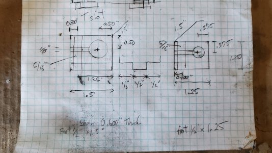
The beam that the T- nuts ride in is a piece of 5/8x1.5" aluminum milled to a thickness of 0.600" the bottom T-Nuts are 1.5x1.5x0.5"/1.25x1.5x0.5" and the T is to a depth of 0.25" so a gap of 0.1" between the opposing T's. I also relieved 0.25" and rounded one end of each the T's to allow maximum travel in the beam channel. Note that the clamping blocks oppose each other when mounted on the beam. A preliminary rough sketch below, squares are 1/4". Ideally I would have preferred to use 7075 because it is less gummy and machines nicely, but this was put together with bits and pieces I had laying around.

The levers I purchased from McMaster-Carr, I just went with longer threads and then turned them down to size on the lathe, I use a washer under the two beam clamping levers.
6271K24 Zinc Adjustable-Position Handle with 5/16"-18 Threaded 2-3/8" Long Stud, 1-13/16" Projection, Black

Cutting oil is Rapid Tap that I use primarily for threading and drilling, on the mill I use a Fogbuster like system with Koolrite 2290 at a 10% emulsion. https://www.hobby-machinist.com/thr...ant-system-with-solenoid-flow-controls.89966/

Vise stop.jpg
 
Mark did it again! After examining his typically precision design and construction, I decided to build one myself. I, too, have a shop-made stop system that rides in the T-slots on the table, and I've shared his frustration on set-up and clean-up. I started out attempting to copy his design exactly, but part way through the project, I discovered I didn't have enough 6061 of sufficient size to make the T-nut assemblies. Bummer.

Consequently, it became necessary to settle on a more spartan version of Mark's stellar design. Here's the result.

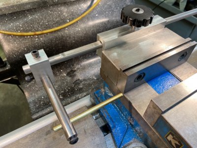
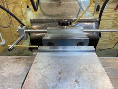
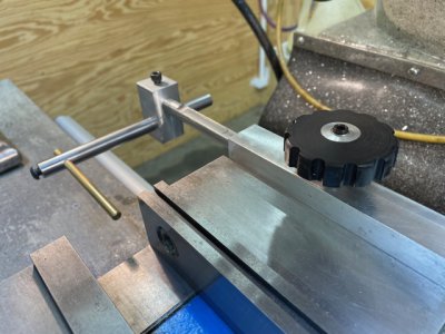
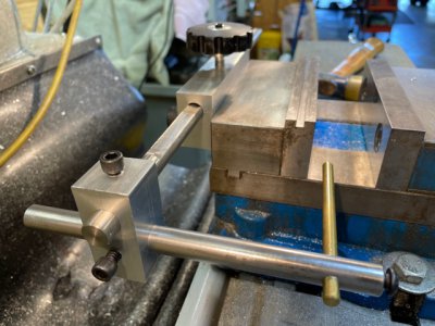
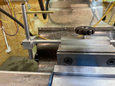
I first made the bracket that mounts to the vise. I made the bar out of 1/2" steel round stock instead of 5/8", solely because it's what I had available. I milled a flat across most of the length that essentially eliminates any possibility of twist. The little hand knob on the back is a stop I made of Delrin and aluminum (a leftover from an earlier project) that I modified to fit in the bracket. That was actually one of the more challenging parts of this project: I needed a very short threaded rod that was 5/16" on one end to fit into the knob, and 3/8" on the other to go into the bracket. Then I made the bar that holds the two T-nut sections from Mark's original design. That's it in the foreground of this photo:
IMG_1779.jpg

Then reality sunk in: I had loads of scrap 6061, but not enough of sufficient thickness to make the T-nut assemblies. Duh. Should have thought of that first. So off to the drawing board I went. I came up with a simple system that requires only one adjustment piece. It attaches to the long rod across the back and transfers to a shorter 1/2" rod parallel to the Y-axis. That was a piece of scrap that had a 3/4" deep 1/4-28 threaded hole that I milled into one end for who-knows-what. I milled a perpendicular 1/4" hole in that end to accept some 1/4" brass rod that I had, and used a socket head screw as a locking device. Turned out great and will work, as is, for most of my applications. The bracket allows for rotating the short rod up or down as necessary, and I can make longer rods in the rare instances where dimensions dictate. And, like Mark's, it can be conveniently rotated vertical when not in use. Here are some photos:
IMG_1774.jpg IMG_1775.jpg IMG_1776.jpg IMG_1777.jpg IMG_1778.jpg

Definitely not up to Mark's high standards of precision and versatility, but it will fit my needs. Mark guided me through much of this build (thanks, Mark), and given that I do not have nearly as high a frequency of projects requiring repeatability, this will likely be adequate for me. It that condition changes, I can procure a little more 6061 and complete the original design.

Regards
 
Very strange error when I tried clicking on one of the images to get a closer look:
Screen Shot 2021-09-10 at 4.26.17 PM.jpg
No problem looking at @mksj's images .... ???
 
Back
Top