935 floor base

Here's my plan- I should be finishing it this week. My intention is to have two machines (PM935 and PM940 CNC) on caster wheels with levelers. Take a look at some snapshots from solidworks for the PM935:

PM935withAngleIron-3.png
PM935withAngleIron-2.png


PM935withAngleIron-1.png
PM935withAngleIron-4.png

PM935withAngleIron-6.png
PM935withAngleIron-5.png


I am using CarryMaster-ALC-1000FB.
CarryMaster-4..jpg
CarryMaster-2.jpg
CarryMaster Caster-ALC-1000FB.png


I"ll post photos once I get this put together on the machine.

Salah
 
I saw your other query about the dimension of the 940. I encourage you to wait on critical dimensions until you have the machines in your possession and can do your own take-offs.
 
I saw your other query about the dimension of the 940. I encourage you to wait on critical dimensions until you have the machines in your possession and can do your own take-offs.
Thank you- that is very wise. I do have both machines in my garage. I will take my own measurements tomorrow. Just wanted to cross-check with someone who also has the machines. The dimensions seem to vary- which is surprising. Maybe they are using different molds when they cast these things.

For the PM935, my measurement is 417.5 mm- I used a scale and it seems to be rougly 16.4375" (16 7/16"). What is your procedure for taking this measurement? I already have 3/4"-10 all-thread going to each leveling feet. So, any measurement I take will have to be using a tape or a scale. It cannot be that accurate. It is difficult to get an accurate measurement when the all-thread is already in place.
 

Attachments

  • IMG_0633.JPEG
    IMG_0633.JPEG
    90 KB · Views: 89
  • IMG_0634.JPEG
    IMG_0634.JPEG
    88.8 KB · Views: 99
  • IMG_0635.JPEG
    IMG_0635.JPEG
    89.3 KB · Views: 94
  • IMG_0636.JPEG
    IMG_0636.JPEG
    90.9 KB · Views: 85
Last edited:
The dimensions seem to vary- which is surprising. Maybe they are using different molds when they cast these things.
The holes are hand drilled after casting. There are no casting drafts or evidence of plugs to suggest otherwise. Plus, this is China. Even in Taiwan today, lots of holes are hand drilled and tapped. Welcome to the dive to the bottom.
 
The holes are hand drilled after casting. There are no casting drafts or evidence of plugs to suggest otherwise. Plus, this is China. Even in Taiwan today, lots of holes are hand drilled and tapped. Welcome to the dive to the bottom.
A dive to the bottom indeed. I just wish the US and others embrace fundamental industries again. I was once driving up around Gary Indiana going to O'Hare airport and someone mentioned the abandoned steel mills in that area. It is a pity to see many supplies, once abundant and of quality, only come from China.

Thank you for the insights you always give and for the meticulous documentation that you keep.
 
Last edited:
Salah, I just looked at your Solidworks drawings. I see what looks like AllThread tie-rods that connect the front and rear platforms together. Those tie-rods may be helpful getting everything assembled, but at least on the 935 they are probably unnecessary once everything is bolted together. If you do employ them, I encourage you to cap the ends with acorn nuts for safety reasons.

Good luck with your build. I considered doing a CNC conversion of the 940, and ended up deciding against it. One of the reasons I abandoned the idea was my friend James experience which he discusses in the first 2-3 minutes of this video. When your 940 does arrive, I encourage you to check the perpendicularly of the various axis movements. Have a look at this video for more info on what/how to check.

David
 
@davidpbest While the ready rod isn't strictly necessary, it will help relieve the stress caused by the angle iron tending to twist downward under load. The bolts do carry that load, but are also holding the machine to the angles, so the ready rod isolates the function in an elegant way.

@szenieh I really like your design! I am doing the same thing on a PM935 (clone), but with a different approach. I'll post my project later this year (when I dig it out) and link you to it. All projects for me are delayed at least 3 months (sigh)
 
@davidpbest While the ready rod isn't strictly necessary, it will help relieve the stress caused by the angle iron tending to twist downward under load. The bolts do carry that load, but are also holding the machine to the angles, so the ready rod isolates the function in an elegant way.
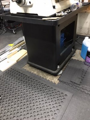
That’s debatable, and totally a function of the scantlings of the angle material. If he uses ¼” 3x4 CRS angle like I did with my implementation, an FEA analysis will show tie rods are unnecessary.
 
That’s debatable,
Of course it is. But I have the right to compliment him on a very well executed design.
tie rods are unnecessary.
Perhaps they are, perhaps not. But my point about isolating forces remains valid. In Engineering, you are taught to recognize all forces, what is in tension and what is in torsion. No need for FEA to do this.

- You may build things any way you choose. I'm pretty sure I'd like your design also.
 
Back
Top