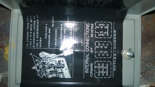
#4 Wire???

The switch you have now is a single phase switch wired for reversing not a three phase switch. Did you connect the blue wire to the switch anywhere? Your motor is a dual voltage motor either 120 volts or 230 volts. It isn't a two speed motor. The high and low refer to the voltage used to power the motor, not the speeds.
 
The wiring schematic in your first post was from my thread here:

http://www.hobby-machinist.com/show...n-a-120V-split-phase-motor-with-a-drum-switch

It's not going to do you a whole lot of good because these motors are different, but the description in my last post might help because it describes what's going on between the switch and the motor.

Ok, you have me confused. :thinking:

What do you mean by high/low? My motor has one speed with forward and reverse. I assume the high/low on your motor is 120V/220V. What is the manufacturer/part number of the motor?

The switch doesn't care how many phases you are using, it's just a 3PDT switch with some jumpers to switch the starter leads around. The main thing is that if you are using 220V, you can't use the stock switch to safely reverse the motor because it doesn't have enough poles, assuming you have a C-H switch like mine. Anyway, for a normal 120V installation your old switch should work fine.

Also, you might want to just get the lathe running in one direction and worry about reverse later? That should be easy to accomplish, basically like wiring a light switch. As long as you have the other wires already run in the conduit, you can come back for reverse later without any difficulty. I ran my lathe for months before I felt I needed to get reverse working.

I have to ask, why did you pitch the working motor that came with the lathe? :whistle:

Old motor smelling a little burnt and because I'm an idiot.
Motor: Baldor Motor L1307M, .75HP, 1725RPM, 1PH, 60HZ, 56, 3428L, OPEN, F1
http://www.globalindustrial.com/site/images/universal/baldor/specs/L1307M.pdf Page 8 is the wiring schematic. Would you mind taking a look at it?


The switch you have now is a single phase switch wired for reversing not a three phase switch. Did you connect the blue wire to the switch anywhere? Your motor is a dual voltage motor either 120 volts or 230 volts. It isn't a two speed motor. The high and low refer to the voltage used to power the motor, not the speeds.

The high/low I'm referring to is on the drum switch cover plate. Stating "Low Range" "High Range".
 
I'm not sure what drum switch you have. On mine, when the knob is pointed down it's open (off). It's marked: Knob to the headstock = forward and knob to the tailstock = reverse. Maybe you want to wait until you get your new drum switch until you tackle the FWD/REV feature. At least the markings on the new switch should be correct.

The motor schematic helps a lot. Your electrician buddy should be able to take it from here, but here's my 2 cents.

You should be able to use your existing switch as a simple on/off. Use a meter and find two electrically separate poles in the switch (you might have to remove an added jumper), that way you can interrupt both the neutral and hot from the plug.

I'm assuming that you are wiring the motor for 120V.

The neutral (white) wire from the plug should go into the switch and then to Terminal 4 (Yellow) of the motor. The hot (black) wire from the plug should go into the switch and then to Terminals 1, 3, 8 (Blue, Orange, Red). Yes, all these wires should be connected together. Then you need to connect together 2, J, 5 (White, Brown, Black).

If all is well, when you plug it in and hit the switch to motor will run correctly. If the breaker pops or the motor smokes, then all is not well. If the motor is running backwards, simply swap the red and black wires.

Just for the record, your motor is completely different from mine (but more typical) with the dual voltage feature and all the wires. Hopefully someone from the silent majority can verify that the above sounds correct.
 
Thanks. I took your advice and just have it running only in one direction for now. It's quiet and smooth. The #4 wire is going straight from the motor to plug connected to the neutral. By-passing the switch.
I'll tackle the reverse later when I get the new switch. My main thing right now is running in the spindle bearings.
 
Sounds good! I'm sure you are dying to get that lathe making chips and reverse can always wait.
 
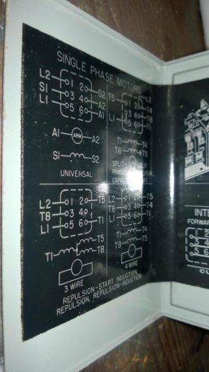
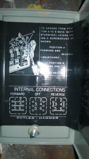
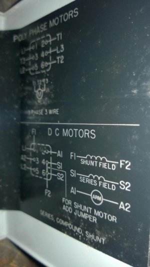
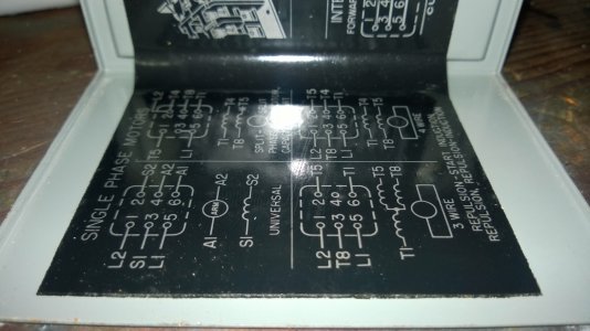
OK. I got the new switch. As you can see my motor is pretty modern I guess. Do I really need to hook up all the leads?
Here is my new switch...Where would the hot line from the plug go along with everything else. :whiteflag:

WP_20150124_001.jpgWP_20150124_002.jpgWP_20150124_003.jpg

WP_20150124_001.jpg WP_20150124_002.jpg WP_20150124_001.jpg WP_20150124_002.jpg WP_20150124_003.jpg
 
https://www.flickr.com/photos/7130897@N03/4970697199/sizes/o/

I used this to get my 10L running with 110V in both directions. I don't see anything to suggest Baldor did not follow the numbering convention in this diagram. Switching 5 and 8 will reverse the direction of travel. Hope this helps. It looks like you were pretty close.

Your original sketch will leave the motor hot. The Wall power should go to the center of the switch, where it will not be in contact with any of the motor circuits while in the off position.

http://www.practicalmachinist.com/vb/south-bend-lathes/need-help-reversing-switch-210013/ had some good info in it.
 
^^^ Thanks but there are no lines in the middle just on the sides.
 
The previous owner of my lathe ran 220V, but couldn't figure out how to run it in reverse.

Using the original switch, wire as per the linked diagram. For a 110V setup, the "Motor 1" will contain wires 1,3,8 if the motor spins clockwise for forward or 1,3,5 if it spins CCW. I forget which it was on the 10L, but I think it might have been CCW. Hot and Neutral Line In are the wall power.

In the linked diagram, your #4 wire is on "Motor 2", so it can go to any of the two lower positions, with a jumper to the other.

I hope that helps. I struggled with wiring mine and eventually learned how motors run in the process. I will say mine works 100% with the diagram I linked.
 
The ''T'' Leads are from the motor, the ''L'' leads are from the wall. L1 is hot, L2 is neutral in a 120 volt circuit.

Use the connection diagram labeled Capacitor Start for wiring.
 
Back
Top