2015 POTD Thread Archive

What I did in my shop today...lost the light from the last remaining 40 inch fluorescent lights. Found that the two light units, (both 8' long) can't be removed by one person, they'll fall before I could remove the last two wingnuts. I've got clip on lights for each machine, but the room is DARK without those lights on the ceiling. I'll live till my 6'5" son comes home to help.
I also started turning the 3" square block for my four-tool tool holder for my Atlas/Clausing 6 by 24 lathe. The interrupted cuts are killing me.
 
my garage/shop got a light upgrade. One LED 4 foot fixture, and one rewired 4 foot dual bulb florescent fixture to dual LED replacements. The one was easy just put cables up and plug it in. The other one I was taking it down to rewire it, and Oh Sh_ _ it dropped to the floor. Looked and it was either purchase a new fixture to rewire for the bulbs, or just replace the bulb holders on the old one as that was what broke, Did not even brake the bulbs. Well Replaced the parts, took out the ballast, the put it back. Now the place lights up like daylight (used the 5000K-6000K bulbs). I has never been that bright in there.
 
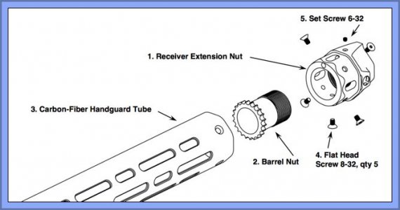
I promised I would post this adapter build in POTD so here it is.

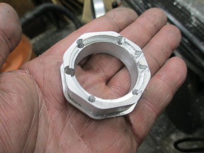
The material is 2 inch round 6061-T6 aluminum and needs to be carved into an octagon shape. This should have been about a one hour project on Monday, but due to a very strange controller program issue and other commitments I didn’t get back to it until today. A quick note on the programming issue: I found a bug in my software, this one had never shown up in the 18 months since I did the upgrade on my mill. There was a logic error in my software that only showed up under an almost impossible set of conditions. This part had exactly the right set of conditions for it to fail. The tool path cut most of the part and then just cut straight across to the other side. That’s why we do air cuts on a new part. It took me a day to figure out what the problem was, and about 20 seconds to fix it in one line of code.

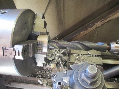
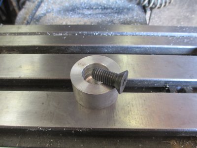
Prepping the blank: The part is 0.593 long, so I cut a chunk fo aluminum about 7/8 long. Through drilled it with a ½ inch drill, the counter sunk to about ¾ deep, for inside tool clearance, to accept the flat head cap screw to secure it to the table.
IMG_0098.jpg

IMG_0099.jpg

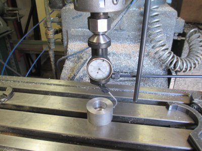
Finding the center

IMG_0100.jpg

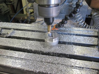
Cutting the outside and inside profile, there are three separate operations here; the outside profile, the base profile, and the inside pocket. This was all done with one tool, I didn’t take picture of all of the operations. Using only the highest quality Harbor Freight 9/16 HSS end mill at 0.500 DOC, 2400 RPM, 10 IPM, about 0.040 step over, with a finish 0.005 step over.
IMG_0101.jpg

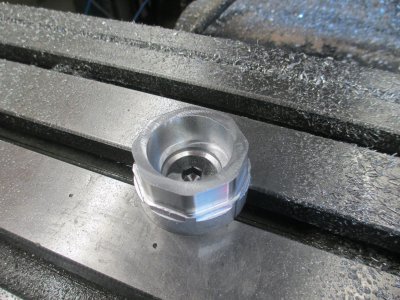
Pocketing and outside profiling finished.
IMG_0102.jpg

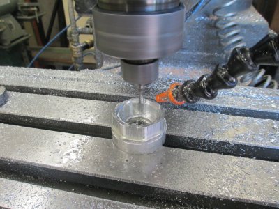
Inside profile, screw clearance and lock tab. 0.125 HSS end mill, 3600 RPM, 6 IPM cutting speed, 0.030 DOC, 0.4 step over, for a total of 0.115 deep.
IMG_0104.jpg

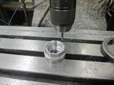
Drilling and tapping 8-32, and one clearance hole. I should have done the drilling and tapping before I did the profiling because of the very thin walls. It worked out OK, I’ll switch the order of operation on the next one. That is what prototypes are for.
IMG_0105.jpg

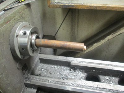
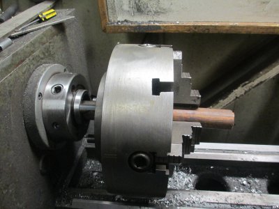
Since this is an octagon, I needed to install the 4-jaw on the lathe. This is a wood dowel I use to control the chuck when removing and replacing. Stick it through the chuck into the spindle, that way the chuck can’t drop and squish my fingers if I lose control of it.
IMG_0106.jpg

IMG_0107.jpg

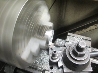
Rough facing off the holding tab, only takes a couple of minutes.
IMG_0108.jpg

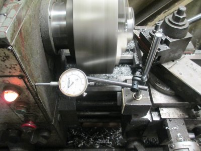
Finishing to length. Measure the part, move over the required amount, and cut.
IMG_0110.jpg

And the finished part before going into the vibratory deburing tub.
IMG_0112.jpg
 
And I thought I was doing good installing two 48" LED overhead lights. There never was so much light in my shop.
 
Gotcha! so I take it the tapped hole are to pin the spurs on the barrel nut.
Mark
 
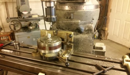
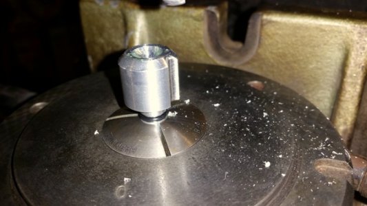
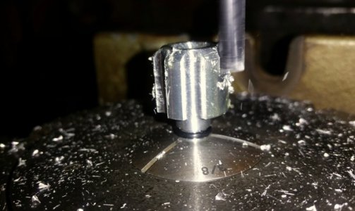
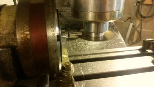
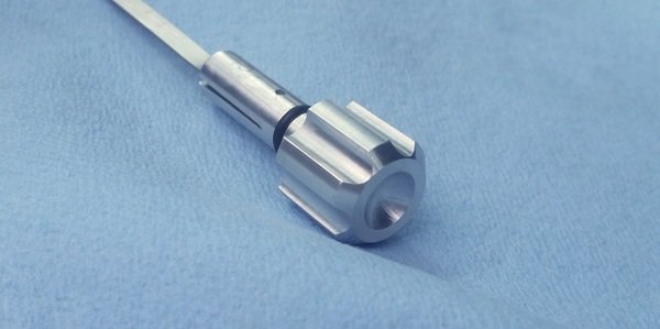
here is a dipstick knob that I made, got to use my new to me Bison rotary super spacer, first (not shown) I turned a 3/4 piece of alu to 3/8ths, then cut an o-ring groove, parted off at the desired length, gripped the 3/8 in the chuck and then took a skim on the OD to clean it up. I stuck a 15/32 ball nose in the tail drill chuck and created a little concave center, then put a 45deg angle. then it was to the mill, and the Bison indexer, I chucked up on the 3/8 end first and used the edge finder to find my edges, chucked a 1/4 end mill and moved the axis to take a little less than half of the end mills diameter, mostly because If I took a full half-width cut it would have cut into the flat on the end. I proceeded to take 6 plunge cuts. happy with the results I swapped to the horizontal position, swapped collets and threw in a slitting saw to make room for the actual dipstick. I drilled the pin holes first. the person on the receiving end was quite happy with the result.
dipstick1.jpg
dipstick2.jpg
dipstick3.jpg
dipstick4.jpg
dipstick5.jpg

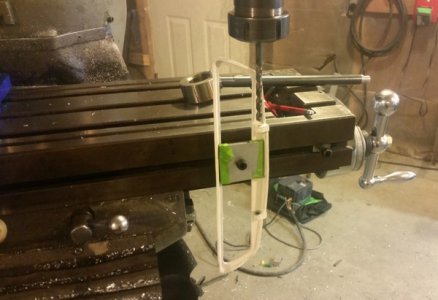
the second project was enlarging the holes in this fiberglass/composite scoop flapper frame, it belongs to a 76 T/A 455HO shaker hood scoop, the factory holes were a little loose around the rod that slips through to retain the metal flapper, the flapper not shown is actuated via solenoids and opens and closes, pretty neat. my test holes it worked great with the bushings, I did it in alu, the bushings were a slight press fit by finger, however the actual job produced a hole that was a few thou over..... but certainly a lot better than it was. I have much to learn about cutting 'glass, it was cool cause it was the first time I had to move the ram over the table to do work, I also had to make T-nuts to fit the front slot on the table, I used a tap in my Albrecht drill chuck to powertap the holes, worked awesome....
flapper1.jpg
flapper2.jpg
 
Nice looking knob design, Chevy.

I never thought of clamping a part to the side grooves.
 
Last edited:
Back
Top