2" x 72" Belt Grinder Kit

I can't comment on the specific model but I will add: If you build it I would make sure you use a 3450 rpm motor (not 1725). You will get much better results with the drive wheel shown.
Robert

Edit: Just realized he used a 3phase motor and a VFD. That's fine too. My comment above would only be relevant if you set it up with fixed speed. You could save a lot of money if you already had a 3450rpm motor.
R

Most do use a 3-phase motor with VFD, but it's still common to see them recommend motors in the 3,450 - 3,600 rpm range. That's probably to keep the RPM up with the bigger contact wheel sizes....just a guess as I haven't gotten that far into the details.
 
I think you want to shoot for a belt speed of 6000 SFPM however you can get there. Check out the specs on a Burr King professional type grinder.
R
 
I’m building the same kit. I watched his YouTube video on the Revolution after I bought the kit I picked up a KBAC 27d and a 3ph 2 hp 3450rpm North American motor. I got just over a 1000 in my build right now, most of the square tubing I had and some I picked up at the scrap yard. In thevideo House made he keeps saying it don’t need tight tolerances but it does, and if you don’t take care with the drilling and the taping. You will need plug taps for the through both side tapped holes because on the regular 3/8-16 the tap shaft won’t go through the first taped side of the 2x2x1/4 wall tube. I had a time getting the tilting hinges to line up so the 3/4 inch main hinge bolt would go through easy. Make sure all your tack welds are solid and strong or when you weld the 90 degree hinge they will move on you and you can’t get the main bolt out with out a BFH. The base and grinding rest will warp real easy when welding. So keep every thing clamped tight. I‘ll be mounting the motor soon and get a run test.
good luck
CH
 

Attachments

  • C19C3EA9-F89E-42E4-B645-D6D5FCB2B010.jpeg
    C19C3EA9-F89E-42E4-B645-D6D5FCB2B010.jpeg
    805 KB · Views: 233
  • FFC4768F-3A68-4BBD-A2A8-F7EB21980480.jpeg
    FFC4768F-3A68-4BBD-A2A8-F7EB21980480.jpeg
    1.2 MB · Views: 231
....
 
Last edited:
All the plates from House are 3/8" thick steel, maybe cold roll. I haven't received the shipment yet. I'll take some pictures when I get started on it.
There are tons of people selling plans, kits, completed machines, etc. Lots of how-to videos on YouTube. House has a lot of competition.
Hi Tmate
The lazar cut parts are not cold rolled. They have heavy mill scale on them. I followed House’s instructions and soaked every thing in white vinegar for 48 hours and then washed them in Simple Green and dried them next to the shop heater. That cut down on rusting. You must do this to get rid of all the scale inside the tubes as well or you will never get the 1.5 inside 2” to slide right and not have a lot of slop and binding. Make sure you have plenty of the belts for the pneumatic 3/8“ belt sander/grinders to clean the the seam weld inside of the tool arm tubes. Try to use steel tubing from the same source like Speedy Metals, I had some 2x2 tubing marked Canada that would not work with 1.5”x1.5x1/4 from Speedy Metals because difference in drawing welding dies. The corners are more rounded, or more square. I also made a cutter called Impossible weld seam remover or something like that over on YouTube. It uses a 3/4” round die grinder bur. To cut the weld out below the surface.
CH
 
Last edited:
Make sure all your tack welds are solid and strong or when you weld the 90 degree hinge they will move on you and you can’t get the main bolt out with out a BFH. The base and grinding rest will warp real easy when welding. So keep every thing clamped tight. I‘ll be mounting the motor soon and get a run test.
I have fought movement after tack welding and assembly welding every time.
Does clamping hold position? It's hard to imagine clamps holding the forces caused from the expansion/contraction of the welding process.
 
The contradictory goals of tack welding is to rigidly and accurately attach two pieces of metal, while at the same time not pumping heat into them. Stainless is Really bad this way. Anyway, the trick is to weld just a little at a time, jumping around the assembly, and also cooling off the work (like with a wet rag) between welds. Anything necessary to keep the assembly cool.
 
Last edited:
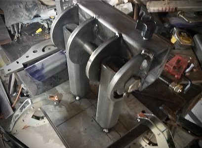
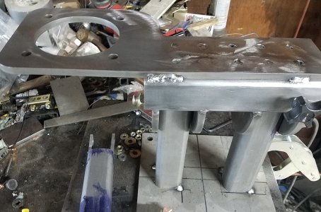
Brian House already has a build video on YouTube which is much more professional than anything I could come up with. I will post some pictures of my build as I go along.

As for the $359 cost: I priced a piece of 3/8" A36 steel plate at Midwest Steel, which has the cheapest prices I could find. A 24" x 36" piece, enough to cut out all brackets with a little to spare, with shipping to me was about $185.00. I'm guessing it would cost at least $50 for the hardware, and maybe more if some parts had to be purchased in multiple quantities. So that's $235.00 not counting shipping for the hardware.

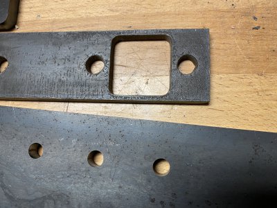
I have a CNC plasma table. However, the plasma process will not produce a cut comparable to the laser cuts House provides. Plasma (excluding high-def plasma, which most of us don't have) produces a noticeable bevel in the cut face. This is particularly apparent in bolt-sized holes.

So, by buying the steel myself, and sourcing all the nuts, bolts, knobs, etc. myself, I could have saved about $125.00. The amount of my time necessary to do all that is worth more than $125.00 to me. Plus the laser cut parts are superior to what I could have done with plasma.

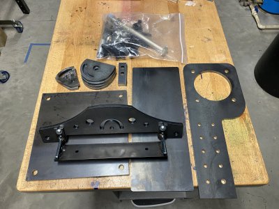
Fist photo shows Brian's kit. I have already welded the platen bracket together. The second photo shows the difference between laser cut holes (bottom) and plasma cut holes (top). The plasma holes are in 1/4" plate, and would have been worse in 3/8".
 

Attachments

  • IMG_8866.JPG
    IMG_8866.JPG
    2.7 MB · Views: 222
  • IMG_8868.JPG
    IMG_8868.JPG
    4.6 MB · Views: 221
Last edited:
Back
Top