- Joined
- Mar 25, 2013
- Messages
- 4,615
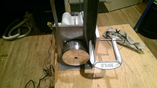
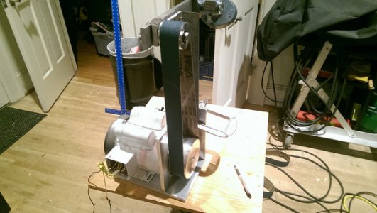
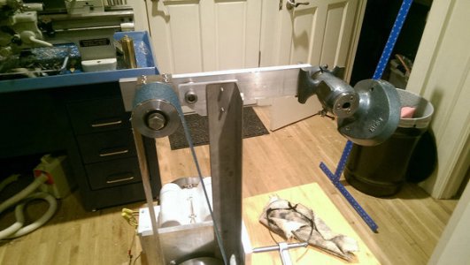
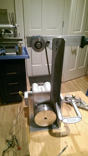
There should be clearance for the angle iron without a problem. I have actually added a 2.5" diameter protective washer to prevent the belt from every contacting the pulley carrier. The 2 x 1/2" aluminum bar will extend off the rear and there will be a tension spring attached to that. That will give me a 3:1 ratio on the belt tension.
Thanks for the pics Mark. I am planning something very similar. What are those table dimensions and are you happy with them?
R
Thanks for the pics Mark. I am planning something very similar. What are those table dimensions and are you happy with them?
R