1/4" Trim Router Extension Shaft

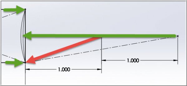
I've often wondered on jaw truing jobs like this - what is the guideline for jaw setting distance before grinding? See sketch. If the jaws were set at say 1" radius (red arrow) & ground, then gripping any stock larger than this equivalent diameter (green arrow) infers the jaw would be contacting the stock at its outer edges & open gap in the middle, no?. OTOH, gripping stock at reduced diameter means it contacts stock at a tangent point in the middle. I wonder how the manufacturer set up the jaws initially? At the half-way range maybe?
11-19-2016 0003.jpg
 
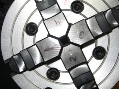
The grinder is an older Dremel flexible shaft that uses a Dremel mounted stone. Nothing special about it except that it fit the tool holder really well. It was run at max speed with the chuck turning at slow speed. The Dremel and flexible shaft were hung over the lathe so that there was very little bend in the shaft. Was patient using the compound at an angle to control d.o.c. in small increments. The fibreglass tape wrapped around the jaws is to catch flying grit and metal. The tape does not in any way load the jaws. There is a foam plug at the inside end of the jaws to prevent grit and metal from getting in the jaw screws.

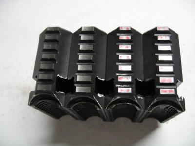
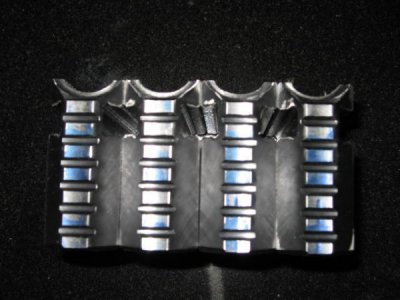
These are the jaws before and after grinding.
IMG_1096.JPG IMG_1113.JPG

There was not much metal to remove to get the jaws parallel to the spindle axis. Please let me know if you have any specific questions.
 
Last edited:
I've often wondered on jaw truing jobs like this - what is the guideline for jaw setting distance before grinding? See sketch. If the jaws were set at say 1" radius (red arrow) & ground, then gripping any stock larger than this equivalent diameter (green arrow) infers the jaw would be contacting the stock at its outer edges & open gap in the middle, no?. OTOH, gripping stock at reduced diameter means it contacts stock at a tangent point in the middle. I wonder how the manufacturer set up the jaws initially? At the half-way range maybe?

You are quite right, too small a radius on the jaw pads would likely mark the work. In my case I wanted the grinding circle to be roughly equal to the spindle bore diameter. The jaws do not hold anything 3/8ths or under but then I use a collet for up to 1/2'' work.

IMG_1138.JPG
 
For tiny stuff that doesn't fit my chuck I clamp a smaller chuck in my three jaw. The smaller chuck is a 4 jaw. Or my tiny three jaw in my large 4 jaw. I might get around to collets some day but I rarely do anything that is more eyeball accuracy. For those times I wish I had them I usually figure out how to use what I already have. There is several projects in line that I do need to be held to tight tolerance by they keep getting posed to the back.

The milling machine is a different story. Most of what I use it for is done to the thou.
 
It was run at max speed with the chuck turning at slow speed.

As long as we're on the jaw grinding subject, I have a thought that I'd like to put out there, to see what others think. I've read many accounts of guys pre loading the jaws in the direction they will be used, and then, WITH THE CHUCK TURNING, run the grinder in and out to not only correct any misalignment with the spindle axis, but also to take some material off of whichever jaw, or jaws is causing runout. But this is on A SCROLL CHUCK. My thought on AN INDEPENDENT JAW CHUCK (4 jaw or ?) is that because each jaw adjusts separately, and you adjust for runout each time you chuck up the work, there is no need to have the chuck turning while grinding. My Plan is to put tension on the jaws toward the ID, then grind one jaw at a time in the 3 o'clock position to correct the off axis angle. If I take more off one jaw than another it shouldn't matter (independent adjusting jaws). If I'm wrong about this please tell me what I'm not seeing. Happy Thanksgiving, JR49
 
Last edited:
JR
If the chuck is not turning you will grind the radius of the stone on the jaws. If the chuck is turning you will get the radius of the turning circle which is larger.
 
My Plan is to put tension on the jaws toward the ID, then grind one jaw at a time in the 3 o'clock position to correct the off axis angle. If I take more off one jaw than another it shouldn't matter (independent adjusting jaws)

I was about to mention that. You beat me to it.
 
If the chuck is not turning you will grind the radius of the stone on the jaws. If the chuck is turning you will get the radius of the turning circle which is larger

You would only have to turn the chuck back and forth a small amount to avoid getting the stone radius.
 
Turning a small amount is turning just the same. Running the lathe at slow speed would be more consistent than turning by hand, at least in my hands it would be :)

And what if the chuck was run at the highest speed so that centrifugal force would load the jaws?
 
Last edited:
Boy, if I had known at the begining what you were doing I would have posted this. My 2 cents are chuck turning as well.
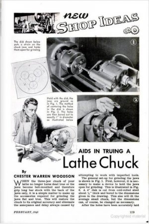
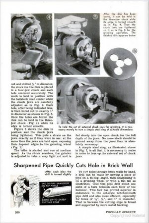
Anyhoo.. here"s something from a 1950's Popular Science & Mechanics.

PopSciMech_2__109.jpg

PopSciMech_2__110.jpg
 
Back
Top